Damper rod bushings as well as gas spring and damper assemblies and methods including same

a technology of damper rod bushings and gas springs, which is applied in the direction of shock absorbers, couplings, other domestic articles, etc., can solve the problems of unsatisfactory influence on the performance and operating characteristics of conventional damper rod bushings

Active Publication Date: 2015-10-01
FIRESTONE IND PROD COMPANY
View PDF9 Cites 24 Cited by
  • Summary
  • Abstract
  • Description
  • Claims
  • Application Information

AI Technical Summary

Benefits of technology

[0011]Another example of a gas spring and damper assembly in accordance with the subject matter of the present disclosure can include a gas spring, a damper and a damper rod bushing. The gas spring can having a longitudinal axis and can include a first end member and a second end member that is spaced axially from the first end member. A flexible spring member extends peripherally about the longitudinal axis between opposing first and second ends. The first end can be secured on the first end member such that a substantially fluid-tight seal is formed therebetween and the second end secured on the second end member such that a substantially fluid-tight seal is formed therebetween with a spring chamber at least partially defined by the flexible spring member and the first and second end members. The damper can extend longitudinally between and operatively connect the first and second end members such that at least a portion of the damper extends through the spring chamber. The damper can include a damper housing operatively connected to the first end member. The damper housing can include a housing wall that at least partially defines a damping chamber. A damper rod assembly can include a damper rod and a damper piston. The damper rod can extend axially between a first end...

Problems solved by technology

As such, direct exposure of known damper rod bushings to pressurized gas from the spring chamber can have...

Method used


Image

  • Damper rod bushings as well as gas spring and damper assemblies and methods including same
  • Damper rod bushings as well as gas spring and damper assemblies and methods including same
  • Damper rod bushings as well as gas spring and damper assemblies and methods including same

Examples


Embodiment Construction

[0021]Turning now to the drawings, it is to be understood that the showings are for purposes of illustrating examples of the subject matter of the present disclosure and are not intended to be limiting. Additionally, it will be appreciated that the drawings are not to scale and that portions of certain features and / or elements may be exaggerated for purposes of clarity and / or ease of understanding.

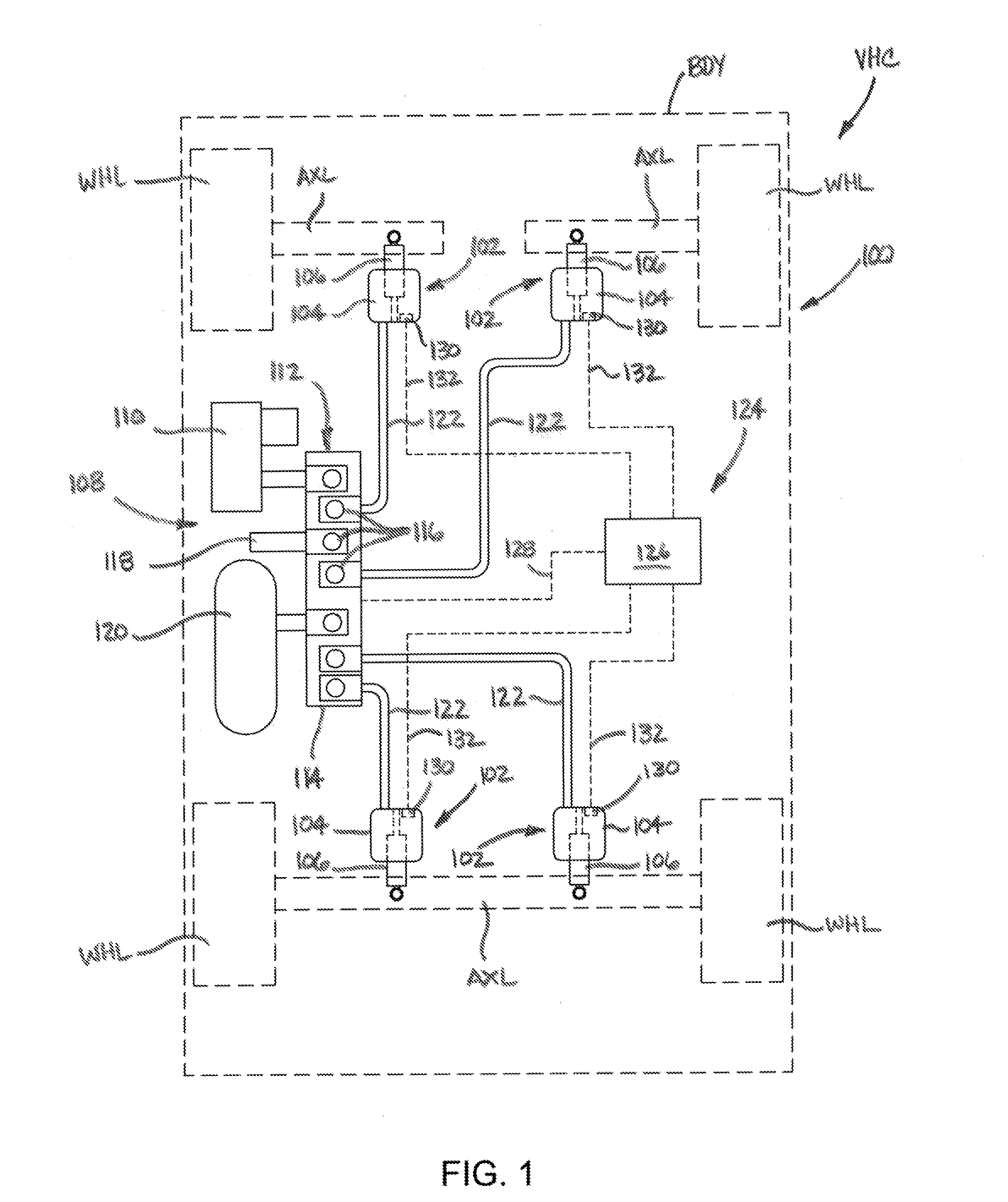
[0022]FIG. 1 illustrates one example of a suspension system 100 disposed between a sprung mass, such as an associated vehicle body BDY, for example, and an unsprung mass, such as an associated wheel WHL or an associated axle AXL, for example, of an associated vehicle VHC. It will be appreciated that any one or more of the components of the suspension system can be operatively connected between the sprung and unsprung masses of the associated vehicle in any suitable manner.

[0023]The suspension system can include any combination spring and damper devices operatively disposed between the spru...


PUM

PropertyMeasurementUnit
Fractionaaaaaaaaaa
Fractionaaaaaaaaaa
Fractionaaaaaaaaaa

Abstract

A damper rod bushing operatively connects an end member of a gas spring and a damper rod of a damper to at least partially form a gas spring and damper assembly. The damper rod bushing is constructed for exposure to gas pressure within a spring chamber of a gas spring and damper assembly such that pre-load forces due to gas pressure within said spring chamber act on said damper rod bushing. The damper rod bushing can include an outer support element, an inner support element and an elastomeric connector element operatively connected between the outer and inner support elements such that a substantially fluid-tight seal is formed therebetween. A gas spring and damper assembly including such a damper rod bushing, as well as a suspension system including one or more of such gas spring and damper assemblies and a method of assembly are also included.

Description

BACKGROUND[0001]The subject matter of the present disclosure broadly relates to the art of gas spring and damper devices and, more particularly, to damper rod bushings dimensioned for securement along an associated end member of an associated gas spring and damper assembly and constructed to accommodate pre-loading associated with direct exposure to pressurized gas contained within the spring chamber of the assembly. Gas spring and damper assemblies can include such a damper rod bushing, and suspension systems can include one or more of such gas spring and damper assemblies. Additionally, damper rod bushings in accordance with the subject matter of the present disclosure can be used in connection with methods of manufacturing gas spring and damper assemblies.[0002]The subject matter of the present disclosure may find particular application and use in conjunction with components for suspension systems of wheeled vehicles, and will be shown and described herein with reference thereto....

Claims


Application Information

Patent Timeline
IPC IPC(8): B60G15/12B23P15/00F16F13/00
CPCB60G15/12F16F13/002B23P15/00B23P2700/14B60G2204/1262B60G2206/80B60G2202/314B60G15/14F16F9/54F16F9/585F16F9/04Y10T29/49615Y10T403/451
Inventor DEBRULER, BRIAN S.MOULIK, PRADIPTA N.LEONARD, JOSHUA R.
Owner FIRESTONE IND PROD COMPANY
Why Eureka
Try Eureka