

Multi-fuel-capable gas turbine combustor
- Summary
- Abstract
- Description
- Claims
- Application Information
AI Technical Summary
Benefits of technology
Problems solved by technology
Method used
Image

Examples
Embodiment Construction
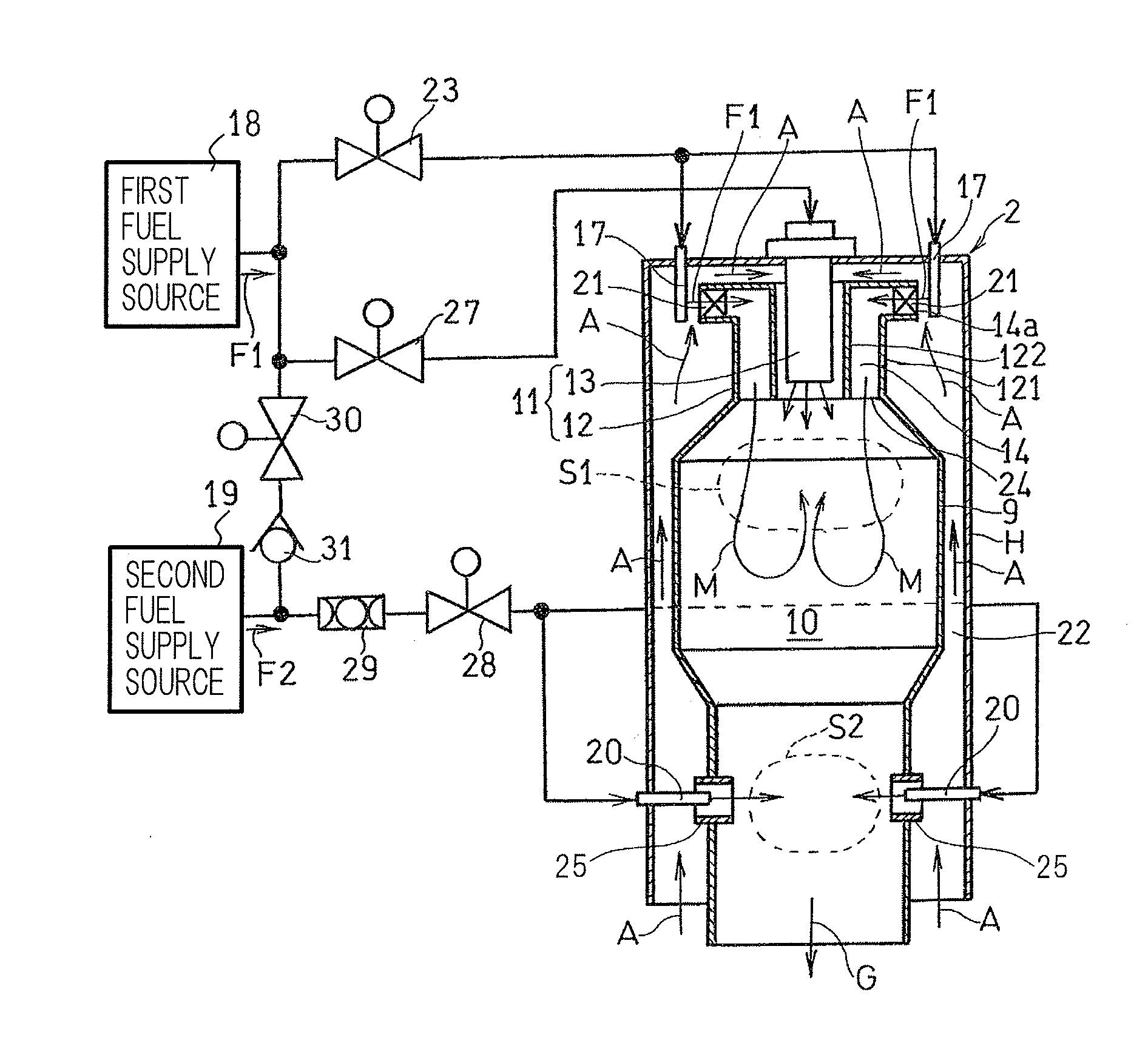
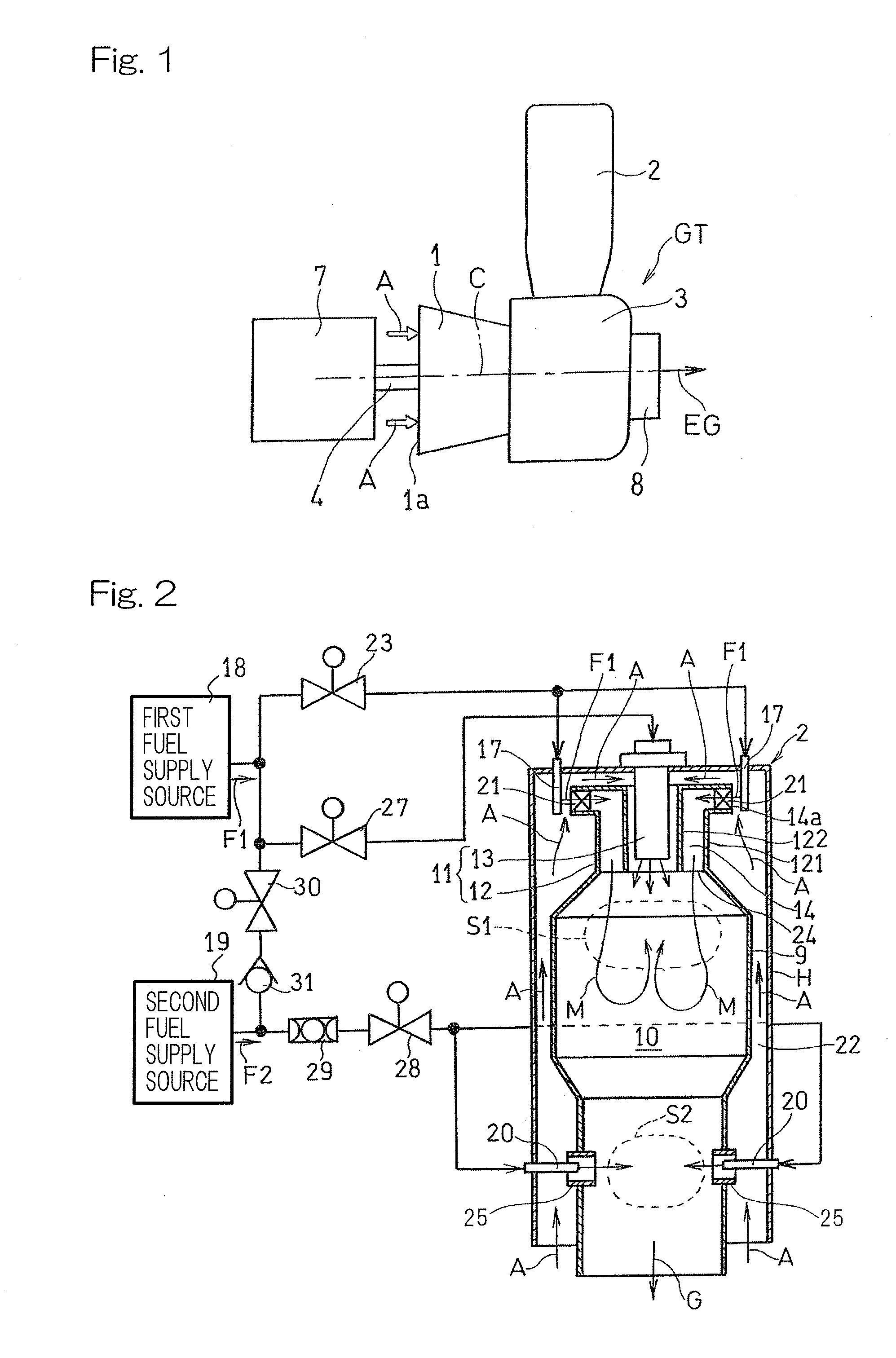
[0026]Hereinafter, embodiments of the present invention will be described with reference to the drawings. In the embodiments of the present invention, a gas turbine engine GT to which a gas turbine combustor is applied is of a single-can type as shown in FIG. 1, but may be of a multi-can type. The gas turbine engine GT includes a centrifugal compressor 1 which compresses air A sucked through an air inflow port la, a combustor 2 which supplies a fuel to the compressed air A and burns the fuel, and a turbine 3 which is driven by a combustion gas from the combustor 2. The combustor 2 is disposed so as to protrude substantially in a radial direction with respect to an engine rotational axis C. The combustion gas generated in the combustor 2 is introduced to the turbine 3 to rotate the turbine 3 to drive: the centrifugal compressor 1 connected to the turbine 3 via a rotation shaft 4; and a load 7 which is, for example, a generator. An exhaust gas EG having passed through the turbine 3 is...
PUM
 Abstract
Description
Claims
Application Information