Damping Valve Arrangement With A Multistage Damping Force Characteristic

a technology of damping force characteristic and damping valve, which is applied in the direction of shock absorbers, vibration dampers, springs/dampers, etc., can solve the problem of difficult to find a compromise in a vibration damper, and achieve the effect of simple construction

Inactive Publication Date: 2015-10-01
ZF FRIEDRICHSHAFEN AG
View PDF6 Cites 1 Cited by
  • Summary
  • Abstract
  • Description
  • Claims
  • Application Information

AI Technical Summary

Benefits of technology

[0008]It is an object of the present invention to develop a damping valve arrangement with a multistage damping force characteristic that has a simple construction and can be adapted to a predetermined damping force characteristic in a more economical way.

Problems solved by technology

It is very difficult to find this compromise in a vibration damper with a conventional, non-electronic damping valve arrangement that is adjustable by an actuator.

Method used


Image

  • Damping Valve Arrangement With A Multistage Damping Force Characteristic
  • Damping Valve Arrangement With A Multistage Damping Force Characteristic
  • Damping Valve Arrangement With A Multistage Damping Force Characteristic

Examples


Embodiment Construction

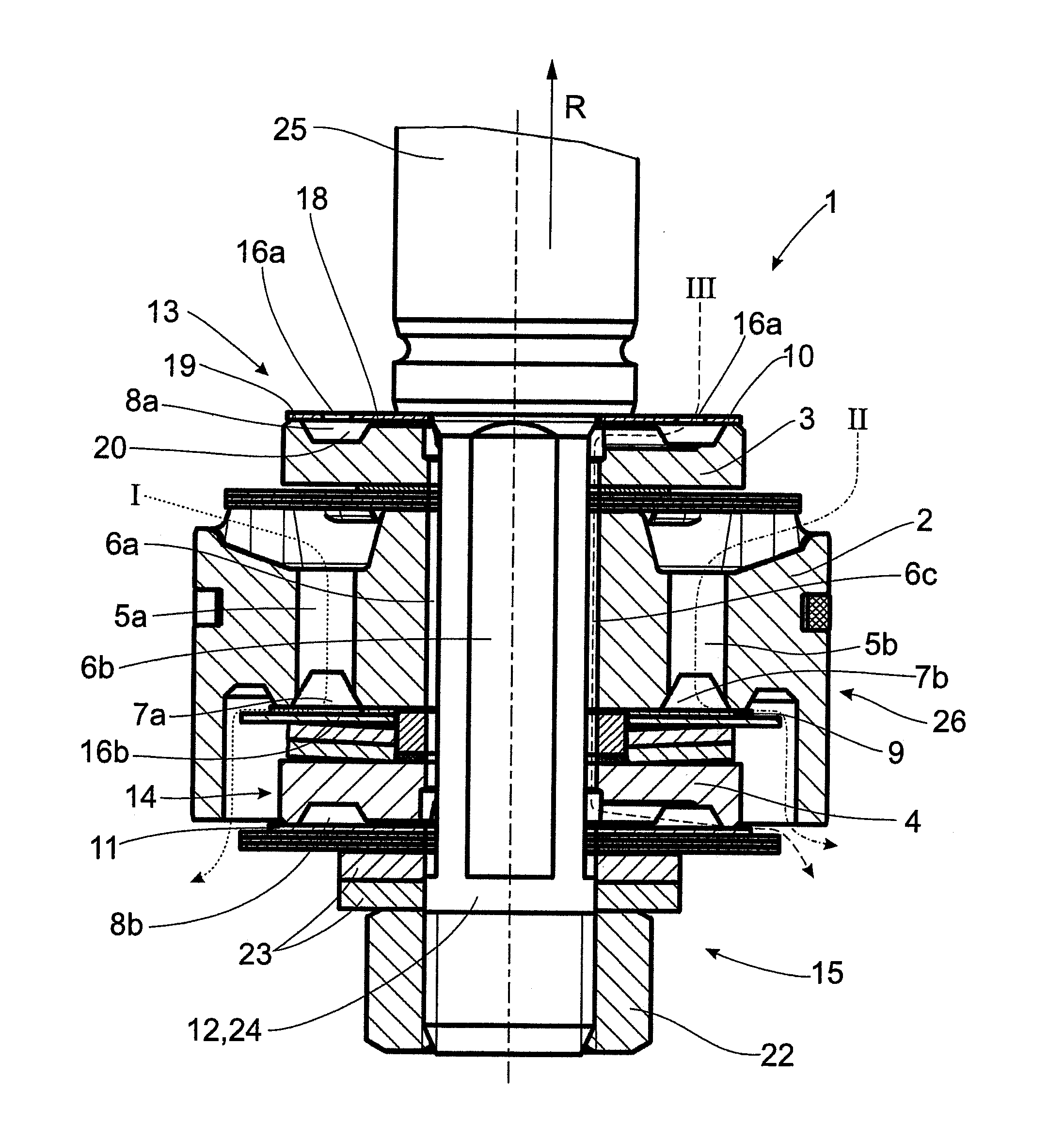
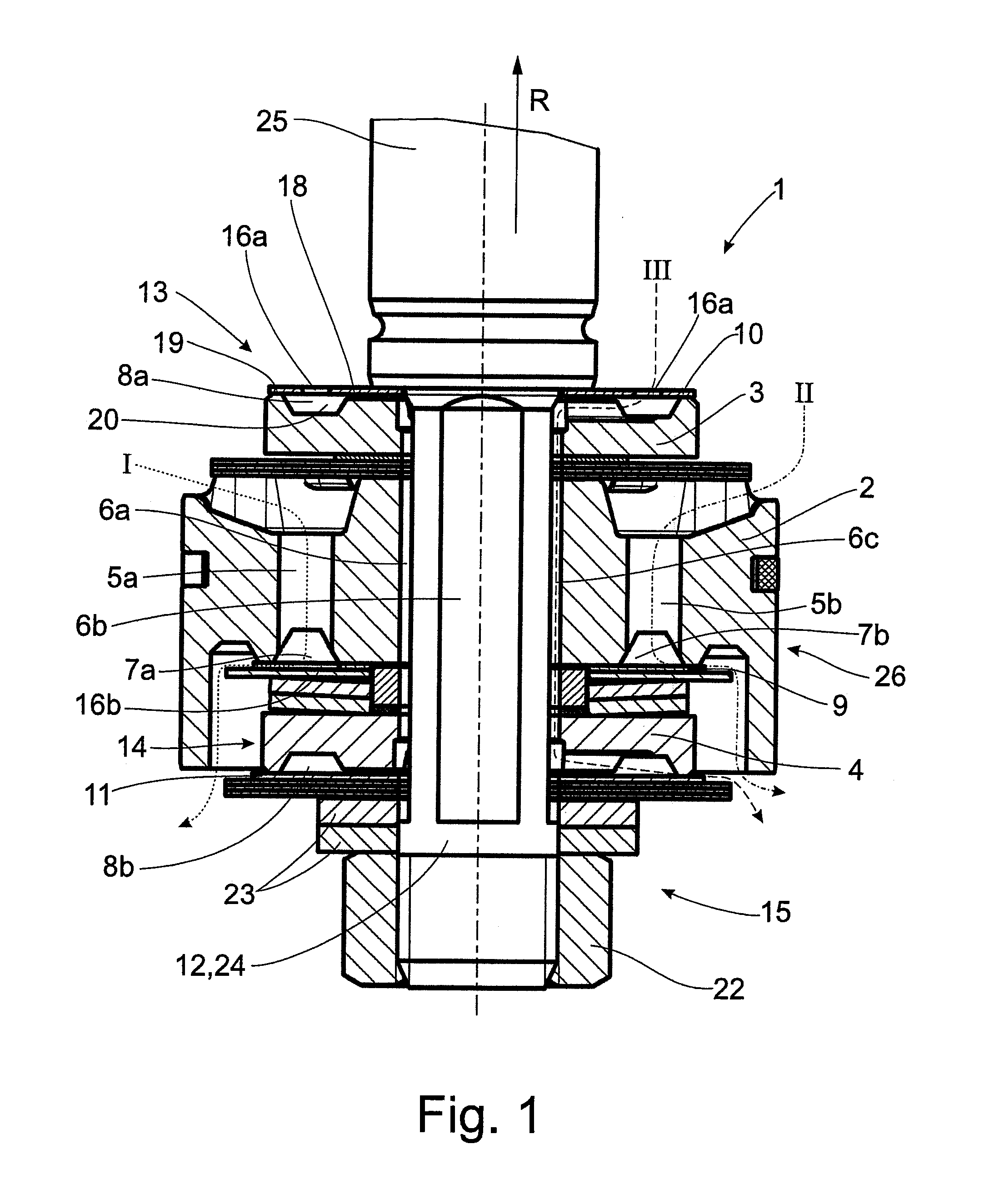
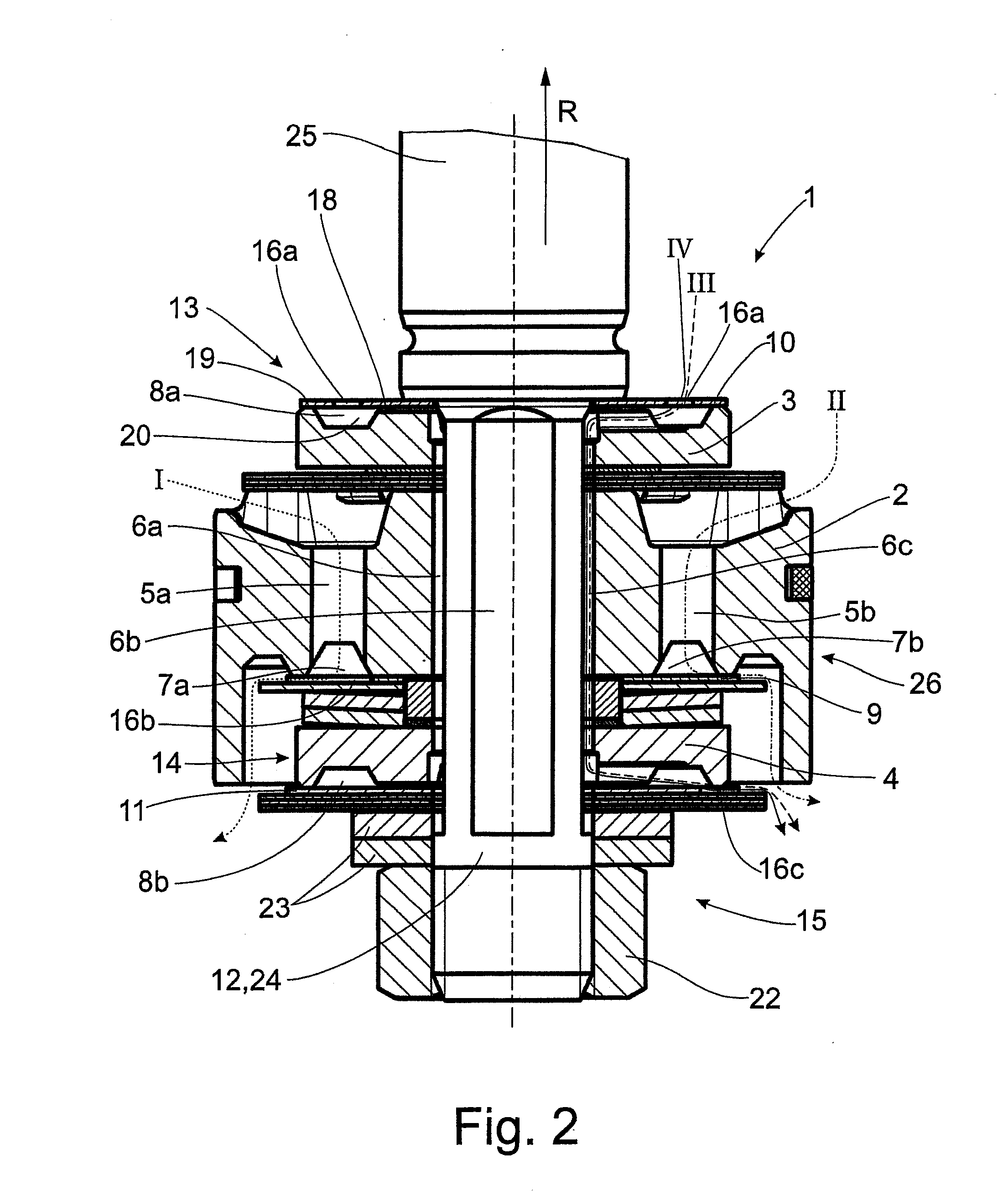
[0023]FIG. 1 shows an exemplary constructional variant of a damping valve arrangement with a multistage damping force characteristic.

[0024]The depicted damping valve device 1 comprises a main valve body 2, a first auxiliary valve body 3, a second auxiliary valve body 4, and a plurality of through-flow channels 5a, 5b, 6a, 6b, 6c connected hydraulically in parallel for a flow direction of a damping medium. The outlet cross sections 7a, 7b, 8a, 8b of the through-flow channels 5a, 5b, 6a, 6b, 6c are influenced respectively by at least one valve disk 9, 10, 11. The valve bodies 2, 3, 4 are axially fastened to a shared support 12, this support 12 extending through the valve bodies 2, 3, 4. As shown in FIG. 1 and FIG. 2, a piston rod neck 24 of a piston rod 25 provides the function of the support 12.

[0025]The positions of the valve bodies 2, 3, 4 are selected such that the main valve body 2 is arranged axially between the first auxiliary valve body 3 and the second auxiliary valve body 4 ...


PUM


Abstract

A damping valve arrangement for a vibration damper has a main valve body, a first auxiliary valve body and a second auxiliary valve body with at least two through-flow channels connected hydraulically in parallel for a flow direction of a damping medium. Outlet cross sections of the at least two through-flow channels are influenced by at least one valve disk. The valve bodies are axially fastened to a shared support that extends through the valve bodies and at least one through-flow channel is formed at the support. A first auxiliary valve including the first auxiliary valve body and at least a first valve disk and a second auxiliary valve including the second auxiliary valve body and a, separate valve disk connected through a shared through-flow channel and are hydraulically connected in series such that the amount of damping medium flowing through the second auxiliary valve is limited by the first auxiliary valve.

Description

BACKGROUND OF THE INVENTION[0001]1. Field of the Invention[0002]The invention is directed to a damping valve arrangement with a multistage damping force characteristic.[0003]2. Description of the Related Art[0004]The object of a vibration damper in a motor vehicle is to damp vibrations due to an uneven road surface. In this regard, there must always be a compromise between driving safety and driving comfort. A vibration damper with a stiff damping valve arrangement having a high damping force characteristic is optimal for highly safe driving. If greater comfort is demanded, the damping valve arrangement should be adjusted to be as soft as possible. It is very difficult to find this compromise in a vibration damper with a conventional, non-electronic damping valve arrangement that is adjustable by an actuator.[0005]A damping valve arrangement with a multistage damping force characteristic having at least four damping force characteristic ranges is known from DE 20 22 021 A1. These da...

Claims


Application Information

Patent Timeline
Patent Type & Authority Applications(United States)
IPC IPC(8): F16F9/348
CPCF16F9/348F16F9/3485F16F9/512
Inventor EICHENMULLER, THOMASMOLLER, ROBERTTREUBERT, MANUELMARKERT, UDO
Owner ZF FRIEDRICHSHAFEN AG
Why Eureka
Try Eureka