Heat source unit of refrigerating apparatus

Active Publication Date: 2015-10-01
DAIKIN IND LTD
View PDF10 Cites 10 Cited by
  • Summary
  • Abstract
  • Description
  • Claims
  • Application Information

AI Technical Summary

Benefits of technology

The invention provides an improved heat sink design that ensures stable heat exchange with the air flow during operation. This is achieved through a process where the air flow passes by the heat-radiating fin without causing degradation in its performance. Additionally, the air flow is stably directed into the first air flow path, ensuring stable heat exchange between the heat sink and the air flow.

Problems solved by technology

In a heat source unit as described above, the air flow sometimes may not stably pass by the periphery of the heat sink, and in such case it is imagined that the performance of the heat sink may degrade.

Method used


Image

  • Heat source unit of refrigerating apparatus
  • Heat source unit of refrigerating apparatus
  • Heat source unit of refrigerating apparatus

Examples


Embodiment Construction

)

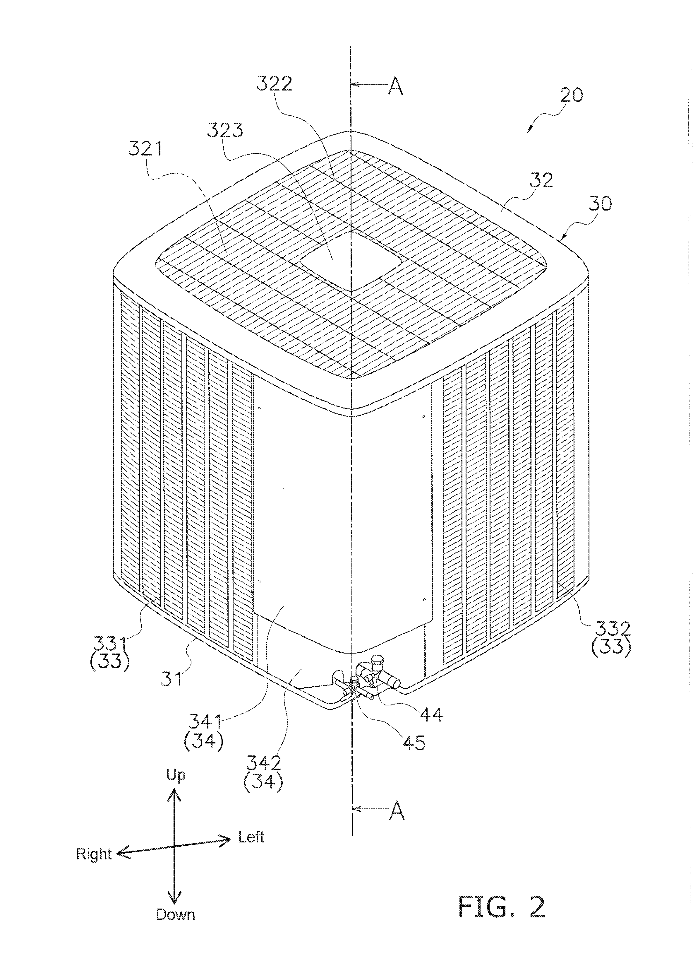
[0029]A heat source unit 20 according to one embodiment of the present invention is described below. The embodiment below is a specific example of the present invention and is not a limitation of the technical scope of the present invention. Suitable modifications may be made within a scope not deviating from the gist of the invention. In the embodiment below, the directions “up,”“down,”“front (front face),”“back (back face),”“left,” and “right” signify the directions illustrated in FIGS. 2 to 13. These directions are directions based on a main face 50a in the condition of placement of a partitioning plate 50 (to be described).

(1) Configuration of the Air-Conditioning Apparatus 100

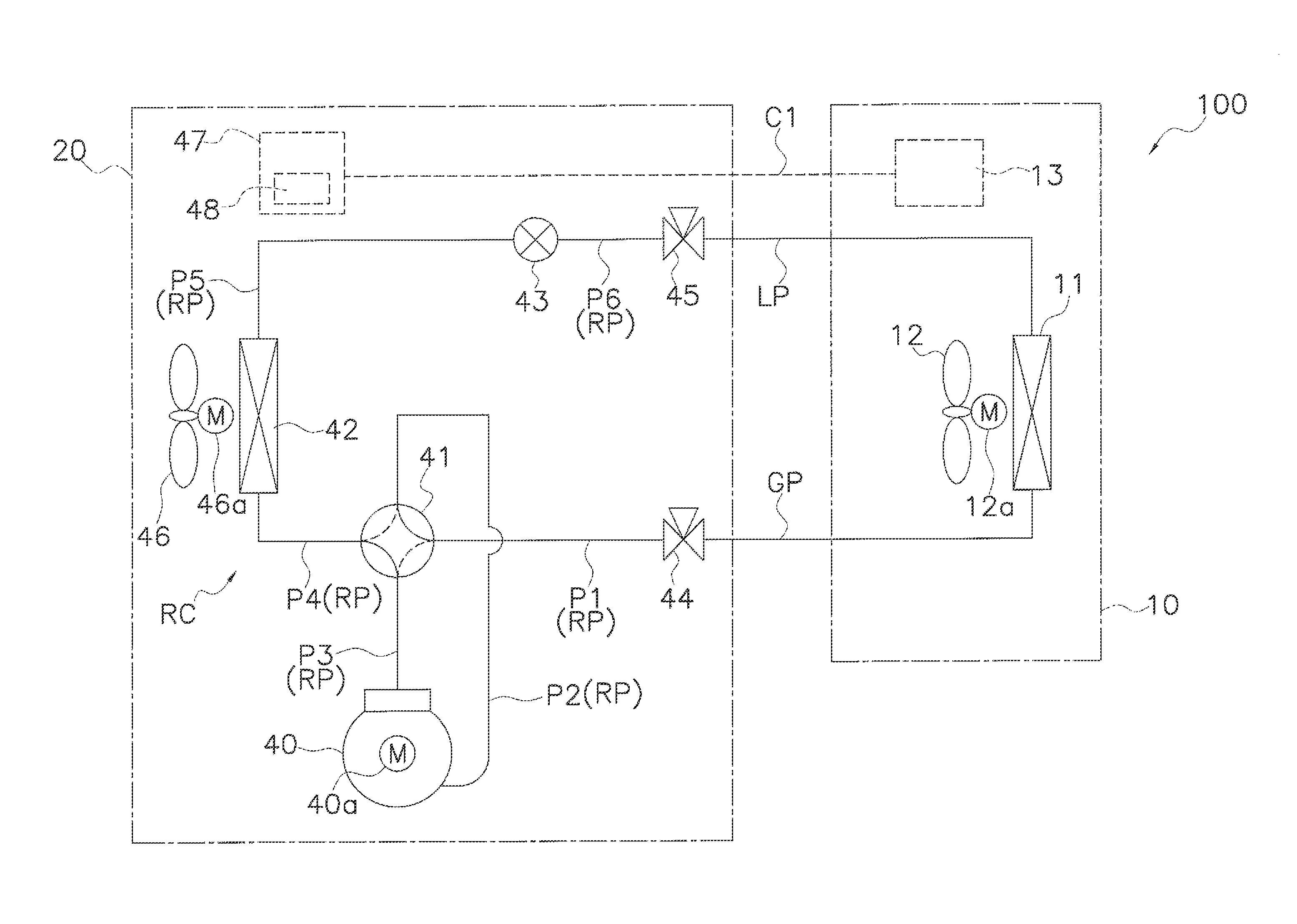
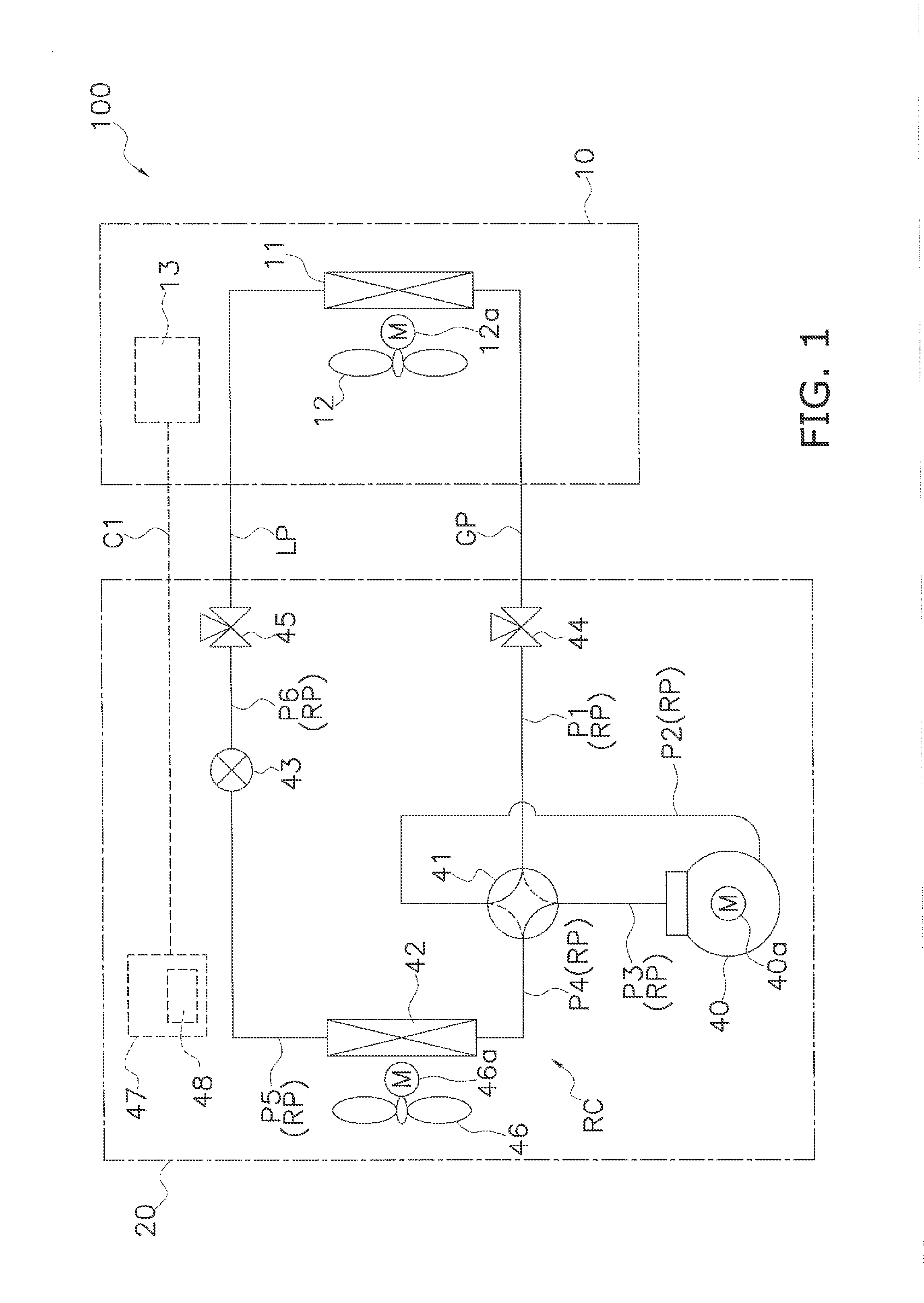
[0030]FIG. 1 is a schematic diagram of an air-conditioning apparatus 100 including a heat source unit 20 according to one embodiment of the present invention.

[0031]The air-conditioning apparatus 100 is an apparatus for performing a cooling operation or a warming operation to realize air conditioning of an...


PUM


Abstract

A heat source unit of a refrigerating apparatus includes a heat exchanger, a blower, an electrical component, a rectifying member, and a casing. The casing houses the heat exchanger, blower, electrical component, and rectifying member. The casing has a vent that vents air upward. The electrical component controls driving of an actuator, and includes a heat-generating part and a heat sink. The heat sink is installed on the heat-generating part, and has a heat-radiating fin. The rectifying member extends along a vertical direction, and covers the heat-radiating fin, and rectifies flow of air. An air inlet is formed on a lower part, and an air outlet on an upper part of the rectifying member. A first air flow path is formed inside the rectifying member. An air flow generated by the blower passes through the first air flow path. The heat-radiating fin is positioned in the first air flow path.

Description

BACKGROUND OF THE INVENTION[0001]1. Field of the Invention[0002]The present invention relates to a heat source unit of a refrigerating apparatus.[0003]2. Background Art[0004]There is a conventional method of cooling a heat sink of an electrical component with an air flow generated by a blower in a heat source unit of a refrigerating apparatus comprising a blower and an electrical component.SUMMARY[0005]In a heat source unit as described above, the air flow sometimes may not stably pass by the periphery of the heat sink, and in such case it is imagined that the performance of the heat sink may degrade. The heat source unit according to the present invention therefore comprises a rectifying member for covering the heat-radiating fin of the heat sink.[0006]Specifically, a heat source unit of a refrigerating apparatus according to a first aspect comprises a heat exchanger, a blower, an electrical component, a rectifying member, and a casing. The electrical component controls driving of ...

Claims


Application Information

Patent Timeline
IPC IPC(8): F24H3/02F24H3/00
CPCF24H3/002F24H3/022F24F1/24F24F1/50
Inventor HAYAKAWA, HIRONORI
Owner DAIKIN IND LTD
Why Eureka
Try Eureka