Secondary battery module with exposed unit cells and insulation between terminals

a secondary battery module and terminal technology, applied in secondary cell servicing/maintenance, batteries, cell components, etc., can solve the problems of difficult manufacturing of structurally strong battery modules using a plurality of such cells, subject to a large number of external impacts and vibrations, and achieve the effect of effectively dissipating heat generated by unit cells and more stably stacked

Active Publication Date: 2011-10-18
LG ENERGY SOLUTION LTD
View PDF15 Cites 7 Cited by
  • Summary
  • Abstract
  • Description
  • Claims
  • Application Information

AI Technical Summary

Benefits of technology

A first object of the present invention is to provide a battery module wherein the size of the battery module can be easily increased or decreased depending upon desired electrical capacity and output, components constituting the battery module and wires for electric connection are constructed in a compact structure while the electrical connection is stably accomplished.
The circuit units may be partially or wholly constructed in a combined structure. Most preferably, the second circuit unit is mounted in the lower receiving part of the lower case, and the third circuit unit is mounted at the other side surface of the module such that the third circuit unit is opposite to the first circuit unit. In this case, the circuit units, which are used to operate the battery, are connected with each other in such a manner that the circuit units surround the battery module according to the present invention, and therefore, the whole size of the battery module is greatly reduced.

Problems solved by technology

Furthermore, devices, which are subject to a large number of external impacts and vibrations, such as electric bicycles and electric vehicles, require stable electrical connection and physical connection between components constituting the battery module.
However, several problems are raised when manufacturing a battery module using the above-described cell as the unit cell.
Specifically, the mechanical strength of the cell sheath (case) is lower, and therefore, it is difficult to manufacture a structurally strong battery module using a plurality of such cells.
Consequently, the size of the battery module is increased, and a manufacturing process of the battery module is complicated.
Also, it is difficult to electrically connect the plate-shaped electrode terminals of the pouch-shaped cell in series or in parallel with each other.
Consequently, a process for electrical connection between the electrode terminals is also complicated.
Also, this connecting process is very complicated.
In addition, the connected parts may separate from each other due to external impacts, which results in increase in the number of defective products.
First, it is difficult to increase or decrease the size of the battery module depending upon desired electrical capacity and output. The unit cells are designed such that the unit cells are suitable for a case having a predetermined size and various components having structures corresponding to the case. Consequently, when unit cells are to be added to increase the output, for example, it is necessary to change the design of the whole battery module.
Furthermore, various components and wires, which are mounted at the outside of the case or provided for electrical connection, are not constructed in a compact structure (high density).
Consequently, the size of the battery module is increased, and the battery module does not provide high safety against external impacts.

Method used


Image

  • Secondary battery module with exposed unit cells and insulation between terminals
  • Secondary battery module with exposed unit cells and insulation between terminals
  • Secondary battery module with exposed unit cells and insulation between terminals

Examples


Embodiment Construction

Now, a preferred embodiment of the present invention will be described in detail with reference to the accompanying drawings. It should be noted, however, that the scope of the present invention is not limited by the illustrated embodiment.

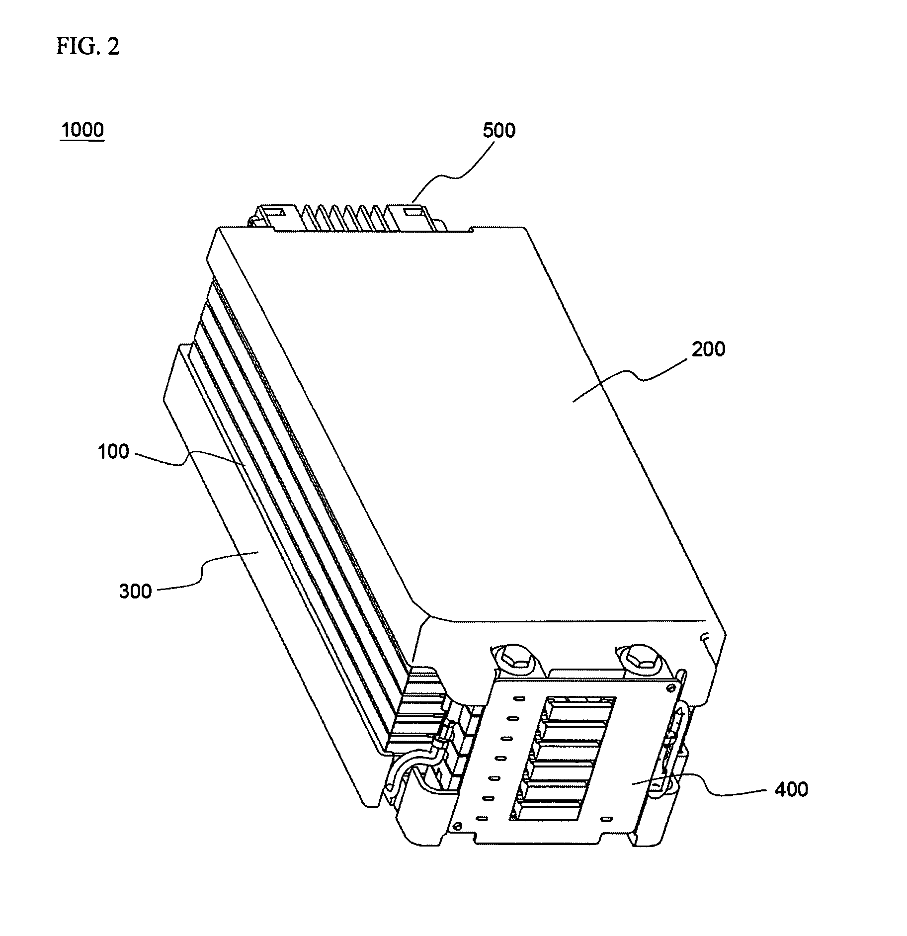
FIGS. 2 and 3 are a typical perspective view and a typical side view respectively illustrating a battery module 1000 according to a preferred embodiment of the present invention.

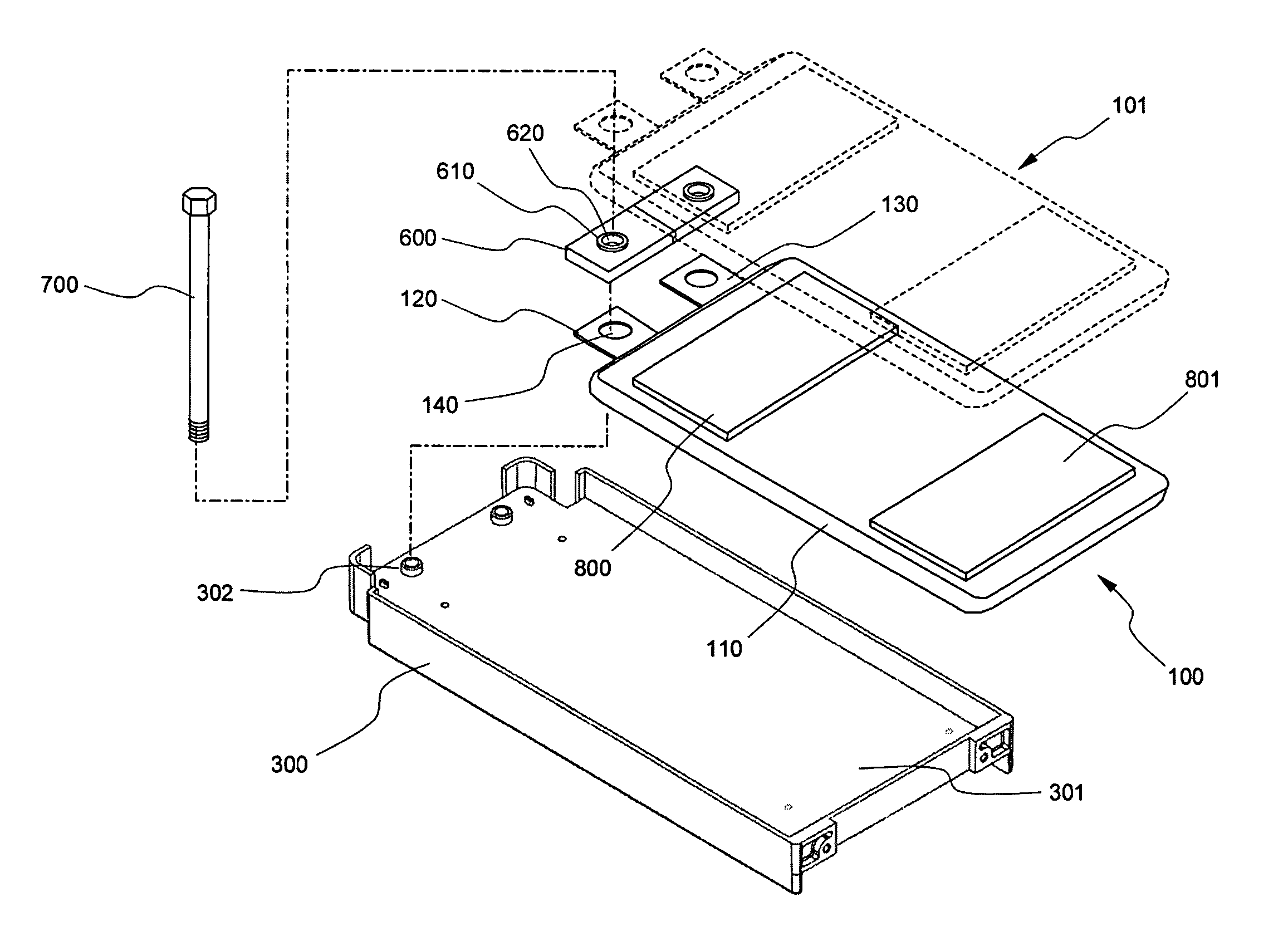
Referring to FIGS. 2 and 3, the battery module 1000 includes an upper case 200, a lower case 300, a plurality of unit cells 100, a first circuit unit 400, a second circuit unit (not shown), and a third circuit unit 500. The unit cells 100 are stacked between the upper case 200 and the lower case 300, which are separated from each other. The first circuit unit 400 is mounted at the front surface of the battery module 1000, the second circuit unit is mounted at the lower surface of the battery module 1000, and the third circuit unit 500 is mounted at the rear surface of the ...


PUM

PropertyMeasurementUnit
voltageaaaaaaaaaa
currentaaaaaaaaaa
temperatureaaaaaaaaaa

Abstract

Disclosed herein is a high-output, large-capacity secondary battery module, having a plurality of unit cells electrically connected to each other, for charging and discharging electricity. A plurality of unit cells are stacked one on another and mounted on a plate, preferably, between an upper case and a lower case, which are separated from each other, circuit units are continuously mounted at the side surfaces of the module for sensing the voltage, the current, and the temperature of the battery, controlling the battery, and interrupting electricity when overcurrent is generated, whereby the secondary battery module is constructed in a compact structure, design of the battery module is easily changed depending upon electrical capacity and output, and components of the battery module are stably mounted.

Description

FIELD OF THE INVENTIONThe present invention relates to a high-output, large-capacity secondary battery module or pack, having a plurality of unit cells electrically connected to each other, for charging and discharging electricity, and, more particularly, to a secondary battery module wherein a plurality of unit cells are stacked one on another and mounted on a plate, preferably, between an upper case and a lower case, which are separated from each other, circuit units are continuously mounted at the side surfaces of the module for sensing the voltage, the current, and the temperature of the battery, controlling the battery, and interrupting electricity when overcurrent is generated, whereby the secondary battery module is constructed in a compact structure, design of the battery module is easily changed depending upon electrical capacity and output, and components of the battery module are stably mounted.BACKGROUND OF THE INVENTIONRecently, a secondary battery, which can be charged...

Claims


Application Information

Patent Timeline
Patent Type & Authority Patents(United States)
IPC IPC(8): H01M2/00H01M2/20H01M50/211H01M50/227H01M50/244H01M50/262H01M50/296H01M50/519H01M50/55H01M50/557H01M50/569H01M50/583H01M50/588H01M50/593
CPCH01M2/0212H01M2/1061H01M2/1077H01M2/206H01M2/30H01M10/0413H01M10/0445H01M10/4207H01M10/425H01M10/482H01M2/34H01M2/0275H01M2200/10H01M50/557H01M50/588H01M50/593H01M50/569H01M50/262H01M50/244H01M50/211H01M50/519H01M50/583H01M50/55H01M50/296H01M50/227Y02E60/10
Inventor HA, JIN WOONGKIM, JEEHOLEE, HANHO
Owner LG ENERGY SOLUTION LTD
Why Eureka
Try Eureka