Secondary battery module

a secondary battery and battery module technology, applied in secondary cell servicing/maintenance, batteries, cell components, etc., can solve the problems of difficult manufacturing of structurally strong battery modules using a plurality of such cells, subject to a large number of external impacts and vibrations, and achieve more stably stacked, effectively dissipate heat generated from unit cells

Active Publication Date: 2006-08-10
LG ENERGY SOLUTION LTD
View PDF12 Cites 74 Cited by
  • Summary
  • Abstract
  • Description
  • Claims
  • Application Information

AI Technical Summary

Benefits of technology

[0028] In a preferred embodiment of the present invention, double-sided adhesive members are disposed between the stacked unit cells. The unit cells are more stably stacked one on another and fixed in the battery module by the double-sided adhesive members. The double-sided adhesive members may be double-sided adhesive tapes, however, the double-sided adhesive members are not limited to the double-sided adhesive tapes. For example, two or more double-sided adhesive members may be disposed on each stacking surface such that the double-sided adhesive members are spaced apart from each other. In this case, predetermined gaps are formed between the stacked unit cells by the double-sided adhesive members. The gaps between the stacked unit cells serve to...

Problems solved by technology

Furthermore, devices, which are subject to a large number of external impacts and vibrations, such as electric bicycles and electric vehicles, require stable electrical connection and physical connection between components constituting the battery module.
However, several problems are raised when manufacturing a battery module using the above-described cell as the unit cell.
Specifically, the mechanical strength of the cell sheath (case) is lower, and therefore, it is difficult to manufacture a structurally strong battery module using a plurality of such cells.
Consequently, the size of the battery module is increased, and a manufacturing process of the battery module is complicated.
Also, it is difficult to electrically connect the plate-shaped electrode terminals of the pouch-shaped cell in series or in parallel with...

Method used


Image

  • Secondary battery module
  • Secondary battery module
  • Secondary battery module

Examples


Embodiment Construction

[0053] Now, a preferred embodiment of the present invention will be described in detail with reference to the accompanying drawings. It should be noted, however, that the scope of the present invention is not limited by the illustrated embodiment.

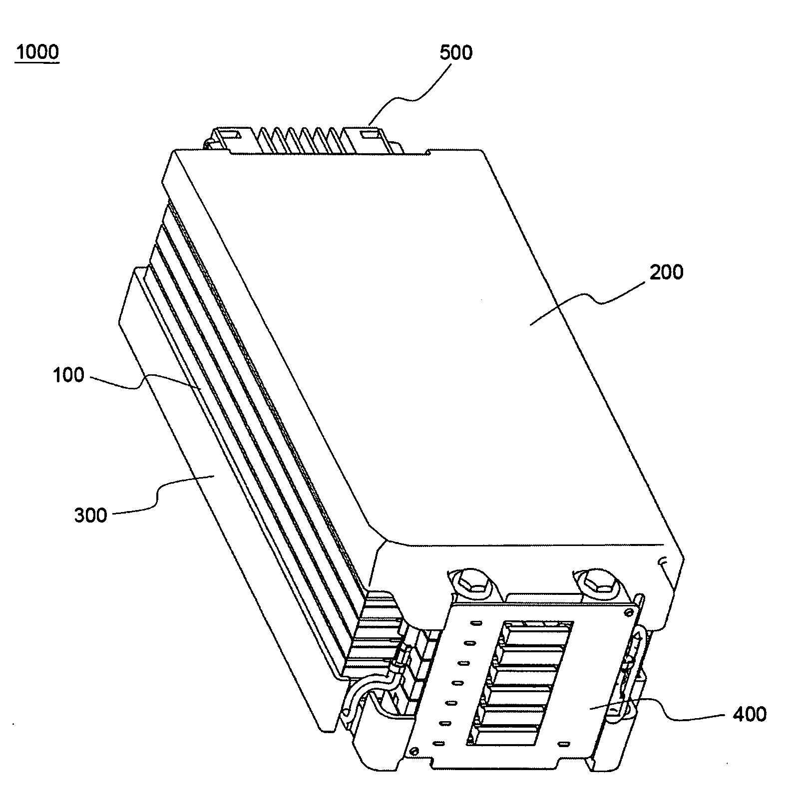
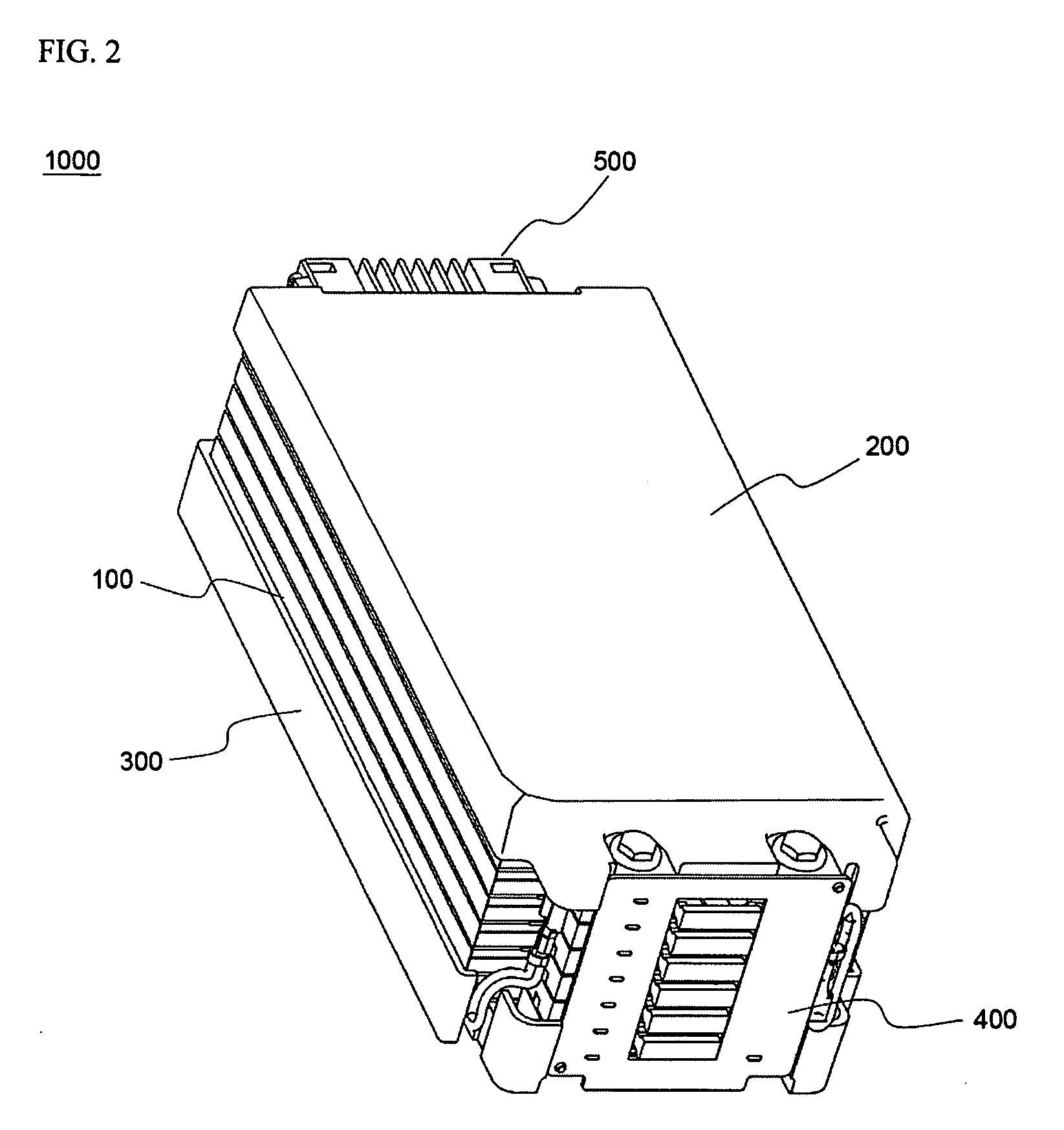
[0054]FIGS. 2 and 3 are a typical perspective view and a typical side view respectively illustrating a battery module 1000 according to a preferred embodiment of the present invention.

[0055] Referring to FIGS. 2 and 3, the battery module 1000 includes an upper case 200, a lower case 300, a plurality of unit cells 100, a first circuit unit 400, a second circuit unit (not shown), and a third circuit unit 500. The unit cells 100 are stacked between the upper case 200 and the lower case 300, which are separated from each other. The first circuit unit 400 is mounted at the front surface of the battery module 1000, the second circuit unit is mounted at the lower surface of the battery module 1000, and the third circuit unit 500 is mounted at th...


PUM


Abstract

Disclosed herein is a high-output, large-capacity secondary battery module, having a plurality of unit cells electrically connected to each other, for charging and discharging electricity. A plurality of unit cells are stacked one on another and mounted on a plate, preferably, between an upper case and a lower case, which are separated from each other, circuit units are continuously mounted at the side surfaces of the module for sensing the voltage, the current, and the temperature of the battery, controlling the battery, and interrupting electricity when overcurrent is generated, whereby the secondary battery module is constructed in a compact structure, design of the battery module is easily changed depending upon electrical capacity and output, and components of the battery module are stably mounted.

Description

FIELD OF THE INVENTION [0001] The present invention relates to a high-output, large-capacity secondary battery module or pack, having a plurality of unit cells electrically connected to each other, for charging and discharging electricity, and, more particularly, to a secondary battery module wherein a plurality of unit cells are stacked one on another and mounted on a plate, preferably, between an upper case and a lower case, which are separated from each other, circuit units are continuously mounted at the side surfaces of the module for sensing the voltage, the current, and the temperature of the battery, controlling the battery, and interrupting electricity when overcurrent is generated, whereby the secondary battery module is constructed in a compact structure, design of the battery module is easily changed depending upon electrical capacity and output, and components of the battery module are stably mounted. BACKGROUND OF THE INVENTION [0002] Recently, a secondary battery, whi...

Claims


Application Information

Patent Timeline
IPC IPC(8): H01M2/10H01M2/04H01M10/42H01M2/08H01M10/50H01M50/211H01M50/227H01M50/244H01M50/262H01M50/296H01M50/519H01M50/55H01M50/557H01M50/569H01M50/583H01M50/588H01M50/593
CPCH01M2/0212H01M2/0275H01M2/1061H01M2/1077H01M2/206H01M2/30H01M2/34H01M10/0413H01M10/0445H01M10/4207H01M10/425H01M10/482H01M2200/10H01M50/557H01M50/588H01M50/593H01M50/569H01M50/262H01M50/244H01M50/211H01M50/519H01M50/583H01M50/55H01M50/296H01M50/227Y02E60/10
Inventor HA, JIN WOONGKIM, JEEHOLEE, HANHO
Owner LG ENERGY SOLUTION LTD
Why Eureka
Try Eureka