Liquid coating apparatus and method thereof

Inactive Publication Date: 2007-09-27
SAMSUNG ELECTRONICS CO LTD
View PDF1 Cites 0 Cited by
  • Summary
  • Abstract
  • Description
  • Claims
  • Application Information

AI Technical Summary

Benefits of technology

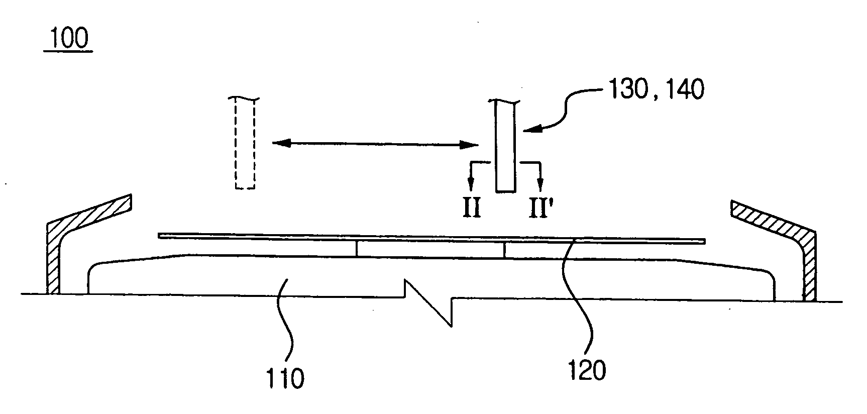
[0007]Example embodiments provide a liquid coating method capable of maintaining a laminar flow around a nozzle and decreasing the strength of a wake and an apparatus using the method.
[0008]Example embodiments also provide a liquid coating method in which a spraying coating may be stably accomplished by reducing and / or minimizing an influence of an air flow and a contamination problem caused by the dispersal of a liquid droplet and an apparatus using the method.
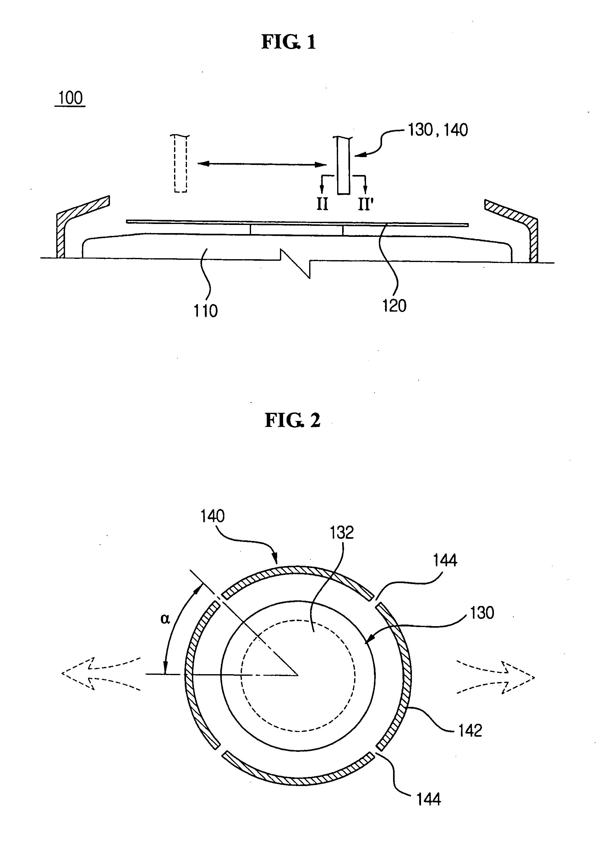
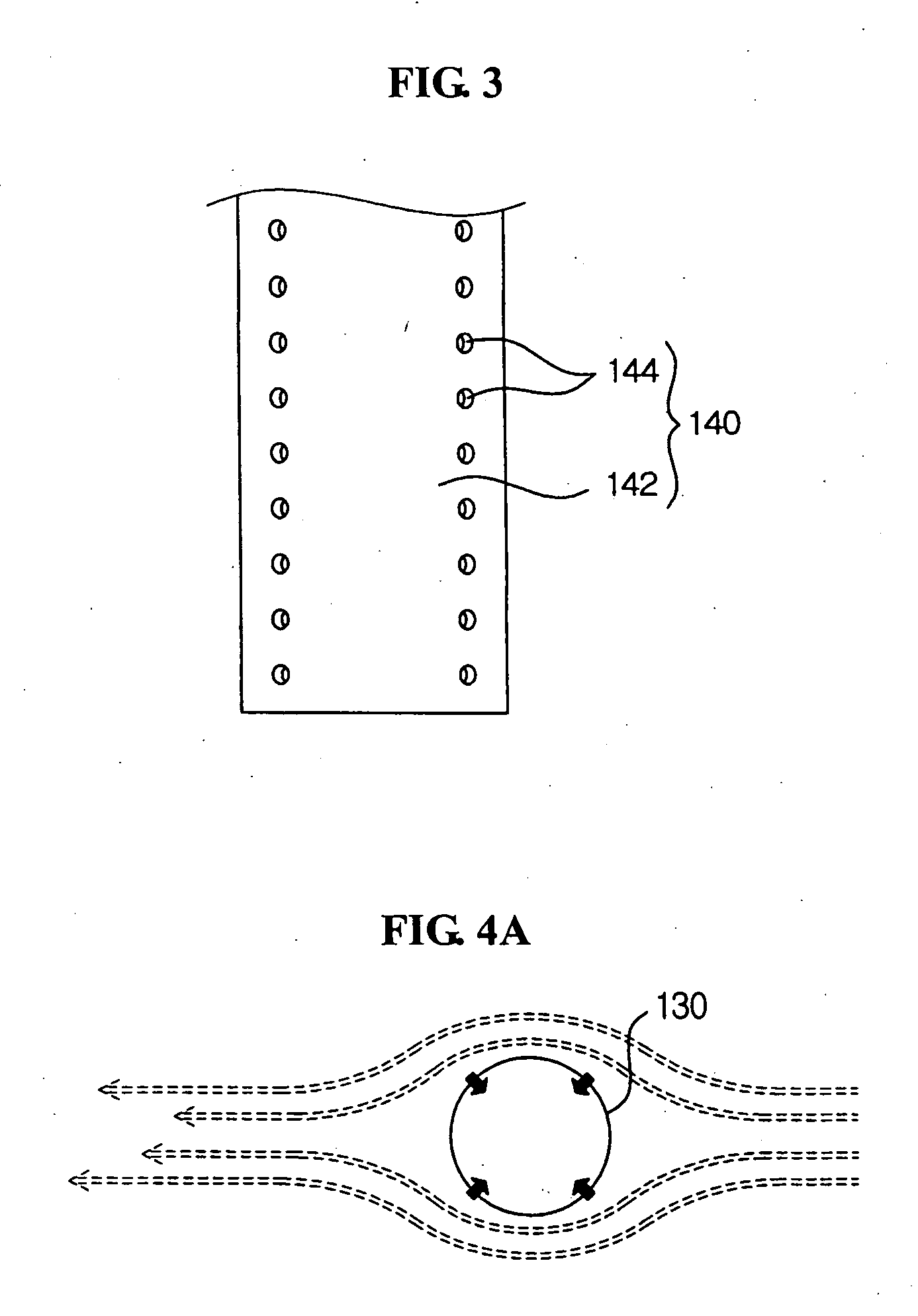
[0011]According to an example embodiment, a laminar flow forming unit may be provided to reduce and / or prevent a wake from forming around the nozzle unit. The laminar flow forming unit may promote a forced air flow to form a laminar flow around the nozzle unit. The forced air flow may be promoted by either suction or blowing of air. In this example embodiment, by forming at least one of a suction hole or a blowing hole around the nozzle unit, a flow separation may be reduced and / or prevented. The suction hole may be formed in a radial shape to reduce and / or prevent the flow separation in a lower portion of the nozzle unit, and the blow hole may reduce and / or prevent the flow separation from occurring in the lower portion of the nozzle unit.
[0012]According to an example embodiment, the laminar flow forming unit may be capable of forming the laminar flow in spite of a wake and thus, the spray coating may stably accomplished.

Problems solved by technology

Accordingly, a large amount of the liquid photoresist may be wasted in a conventional spin coating method.
Further, the dispersed liquid photoresist may contaminate adjacent equipment.
However, in a conventional spray coating method using a conventional spray coating apparatus, a wake may occur around a spray nozzle during the spray coating process because of a downflow descending from a top surface of a substrate and nozzle transferring.
Furthermore, liquid photoresist not coated on the wafer may contaminate the adjacent equipment.

Method used


Image

  • Liquid coating apparatus and method thereof
  • Liquid coating apparatus and method thereof
  • Liquid coating apparatus and method thereof

Examples


Embodiment Construction

[0029]Example embodiments are described more fully hereinafter with reference to the accompanying drawings. Embodiments may, however, be in many different forms and should not be construed as limited to the example embodiments set forth herein. Rather, these example embodiments are provided so that this disclosure will be thorough and complete, and will fully convey the scope to those skilled in the art. In the drawings, the size and relative sizes of components may be exaggerated for clarity.

[0030]It will be understood that when a component is referred to as being “on,”“connected to” or “coupled to” another component, it can be directly on, connected to or coupled to the other component or intervening components may be present. In contrast, when a component is referred to as being “directly on,”“directly connected to” or “directly coupled to” another component, there are no intervening components present. As used herein, the term “and / or” includes any and all combinations of one or...


PUM

PropertyMeasurementUnit
Angleaaaaaaaaaa
Angleaaaaaaaaaa
Forceaaaaaaaaaa

Abstract

A liquid coating apparatus and method for spraying a liquid on a wafer. The liquid coating apparatus may include a nozzle unit spraying the liquid on the wafer and moving relative to the wafer and a laminar flow forming unit forming a forced air flow around the nozzle unit. Though a wake may be formed around the nozzle unit by a movement of the nozzle unit, the laminar forming unit may reduce and / or minimize an influence of the wake.

Description

PRIORITY STATEMENT[0001]This application claims the benefit of priority to Korean Patent Application No. 10-2006-0026057, filed on Mar. 22, 2006, in the Korean Intellectual Property Office, the entire contents of which is incorporated herein by reference.BACKGROUND[0002]1. Field[0003]Example embodiments relate to a liquid coating apparatus and method of spraying liquid on a target object. More particularly, example embodiments relate to a liquid coating apparatus and liquid coating method for evenly spraying one or more micro droplets on a wafer.[0004]2. Description of Related Art[0005]Conventionally, a spin coating method has been utilized for coating a liquid photoresist on a wafer. According to the conventional spin coating method, an amount of the liquid photoresist may be dropped above a rotating wafer and a centrifugal force may cause the liquid photoresist to be spread and coated on the wafer. In the conventional spin coating method, a large amount of the liquid photoresist i...

Claims


Application Information

Patent Timeline
IPC IPC(8): B05C11/02B05B3/00B05D7/00B05D3/12
CPCB05D1/005H01L21/6715G03F7/162B05D1/02G10K9/22G10K9/12
Inventor LEE, JIN SUNGKIM, TAE GYUKOO, JUNE MOJUNG, CHANG HOON
Owner SAMSUNG ELECTRONICS CO LTD
Why Eureka
Try Eureka