
Method and Engine for Identifying Events in a Sensor Signal Using Rate-Dependent Feature Sets

a technology of event attributes and feature sets, applied in the field of event attributes identifying in sensor signals, can solve the problems of degrading the performance of event attributes, unable algorithms executed by electronic monitoring devices routinely fail to account for the rate dependence of event attributes, so as to improve the identification of respiration segments and improve the effect of event identification

Inactive Publication Date: 2015-10-01
SHARP LAB OF AMERICA INC
View PDF2 Cites 1 Cited by
  • Summary
  • Abstract
  • Description
  • Claims
  • Application Information

AI Technical Summary

Benefits of technology

The present invention provides a way to identify events in a sensor signal using multiple feature sets that are influenced by the rate at which the events occur. By comparing the feature sets with quality benchmarks, the method and engine can determine which ones are producing reliable results and which ones are not. This enables electronic monitoring devices to make better event identifications by using only the reliable feature sets and discarding unreliable ones. This technology is particularly useful for respiration monitoring devices, where it can improve the identification of respiration segment boundaries.

Problems solved by technology

However, a common weakness of these algorithms is failure to account for the dependence of event attributes on the rate at which the events occur.
Yet segment identification algorithms executed in many respiration monitoring devices fail to account for these and other rate dependencies, degrading their performance.
Perhaps one reason that algorithms executed by electronic monitoring devices routinely fail to account for the rate dependence of event attributes is that event attributes and the rate at which events occur are mutually dependent.

Method used


Image

  • Method and Engine for Identifying Events in a Sensor Signal Using Rate-Dependent Feature Sets
  • Method and Engine for Identifying Events in a Sensor Signal Using Rate-Dependent Feature Sets
  • Method and Engine for Identifying Events in a Sensor Signal Using Rate-Dependent Feature Sets

Examples


Embodiment Construction

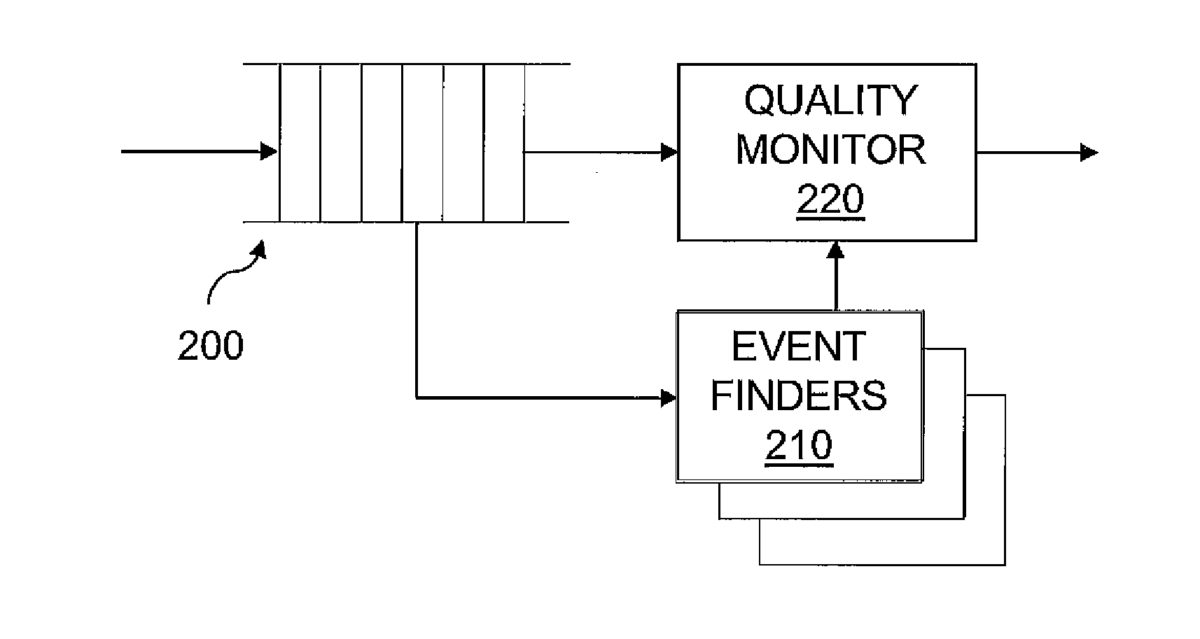
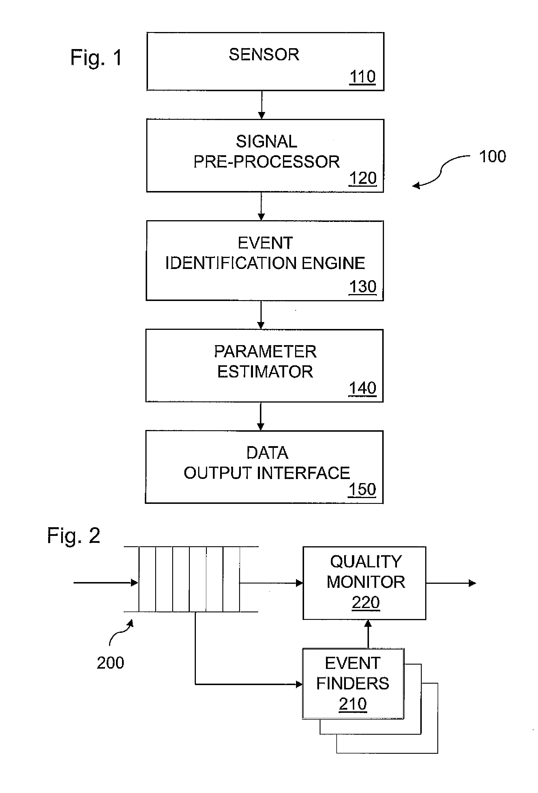
[0025]FIG. 1 shows an electronic monitoring device 100 in some embodiments of the invention. Device 100 has a sensor 110 that generates a sensor signal having samples that record events being monitored. Sensor 110 may take various forms. For example, sensor 110 may be an acoustic sensor having a microphone capturing sounds associated with events. Alternatively, sensor 110 may detect changes in condition, such as changes in position (movement), air pressure or density, associated with events. Sensor 110 continually transmits a sensor signal waveform to signal preprocessor 120.

[0026]Signal preprocessor 120 preprocesses the sensor signal waveform received from sensor 110 to prepare the signal for processing by event identification engine 130. Preprocessor 120 extracts signal attributes from the sensor signal waveform to yield feature vectors. Each feature vector characterizes a segment of the signal over a predetermined time interval in terms of attributes useful for event identificati...


PUM


Abstract

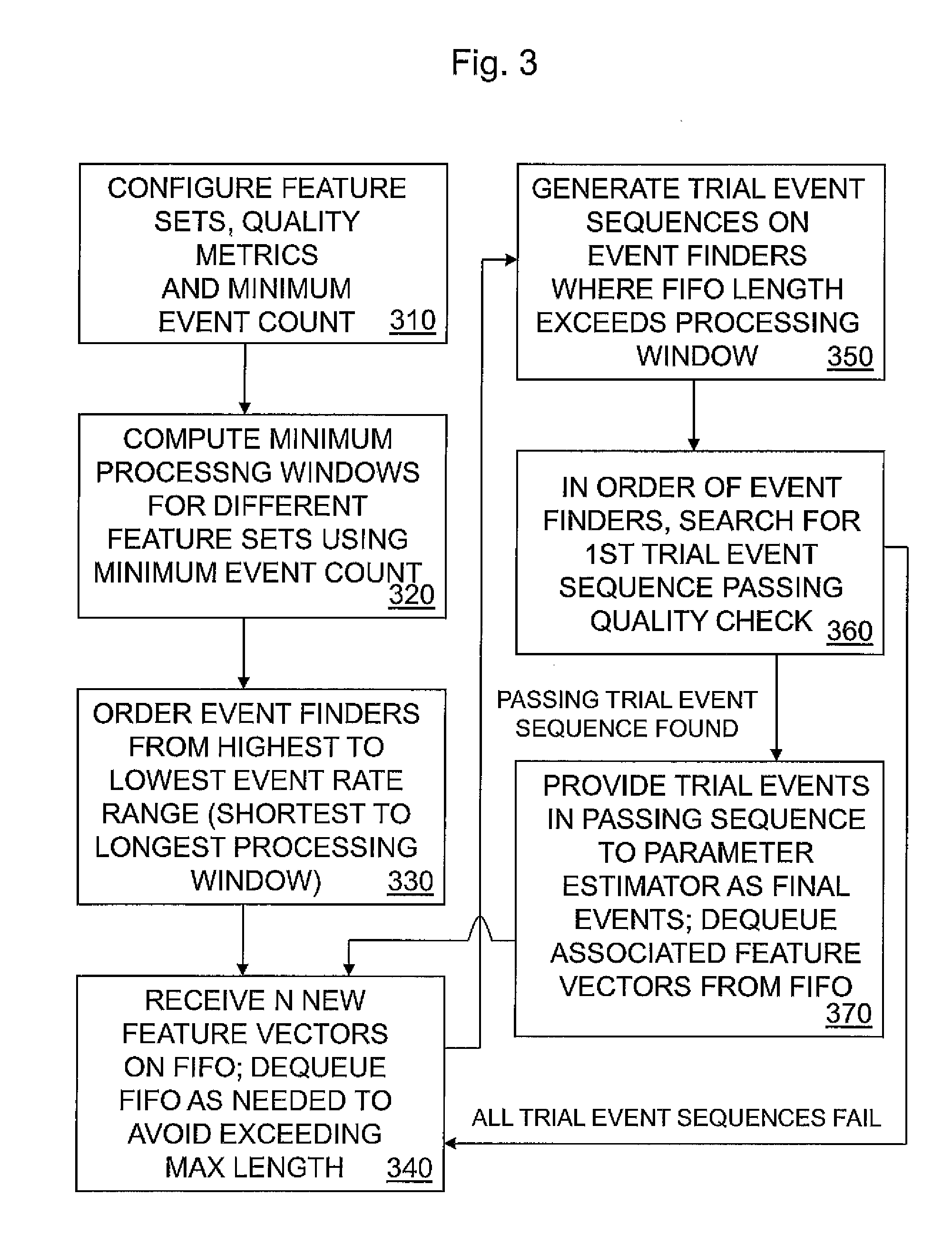
A method and engine for identifying events in a sensor signal using rate-dependent feature sets couples trial event identifications made using different rate-dependent feature sets with rate-dependent quality assessments to overcome the mutual dependency of event attributes and the rate of events. The quality assessments compare event identifications made at different rates against quality benchmarks for event identifications at those rates, such as event stability benchmarks, to determine which feature sets are producing reliable event identifications and which are not. The invention enables electronic monitoring devices to make improved event identifications by accepting identifications made by presently reliable rate-dependent feature sets and rejecting those made by presently unreliable rate-dependent feature sets. In one application of the invention, the method and engine enable a respiration monitoring device to make improved respiration segment identifications.

Description

BACKGROUND OF THE INVENTION[0001]The present invention relates to identification of events in a sensor signal and, more particularly, identifying respiration segments in a body sensor signal.[0002]Many electronic monitoring devices identify events of interest in a sensor signal and perform analysis on those events. An example of such an electronic monitoring device is a respiration monitoring device.[0003]Respiration is an important vital sign. Abnormal breathing, as reflected by a high or low respiration rate or inspiration to expiration ratio (I:E) or other respiration parameter, can indicate a current or imminent acute health problem, such as an asthma attack or cardiac arrest. Respiration monitoring devices monitor breathing in real-time to enable timely detection of these problems.[0004]Different kinds of respiration monitoring devices are known. One class of devices monitors end-tidal carbon dioxide (EtCO2) expelled by a patient. Another monitors air pressure through the patie...

Claims


Application Information

Patent Timeline
Patent Type & Authority Applications(United States)
IPC IPC(8): G06F19/00G16Z99/00
CPCG06F19/3406A61B5/0816G16H40/63G16Z99/00
Inventor HILL, FREDRICK NORMAN
Owner SHARP LAB OF AMERICA INC
Learn More