
Removable lift assembly for a rotorcraft, and a rotorcraft

a technology of rotorcraft and lift assembly, which is applied in the direction of rotorcraft, aircraft components, aircrafts, etc., can solve the problems of reducing the ground clearance of the blades of the main rotor, affecting the drag generated by the rotorcraft in forward flight, and difficult to arrange the propellers under the main rotor. to achieve the effect of reducing the drag of the rotorcraft and low drag

Active Publication Date: 2015-10-08
EUROCOPTER
View PDF38 Cites 43 Cited by
  • Summary
  • Abstract
  • Description
  • Claims
  • Application Information

AI Technical Summary

Benefits of technology

The patent describes a lift assembly that can be used to create a modular rotorcraft. This means that the rotorcraft can be designed with just one module containing the fuselage and another module containing the lift assembly. This design allows for easier assembly and maintenance of the rotorcraft.

Problems solved by technology

Nevertheless, such an arrangement reduces the ground clearance of the blades of the main rotor.
On a rotorcraft that is provided both with a rotor and with propellers, it can then be difficult to arrange the propellers under the main rotor for the purpose of contributing in particular to propelling the rotorcraft and / or to controlling yaw movement of the rotorcraft.
Such an arrangement can have a negative impact on the drag generated by the rotorcraft in forward flight.
Furthermore, a wing is usually fastened to the fuselage in non-removable manner.

Method used


Image

  • Removable lift assembly for a rotorcraft, and a rotorcraft
  • Removable lift assembly for a rotorcraft, and a rotorcraft
  • Removable lift assembly for a rotorcraft, and a rotorcraft

Examples


Embodiment Construction

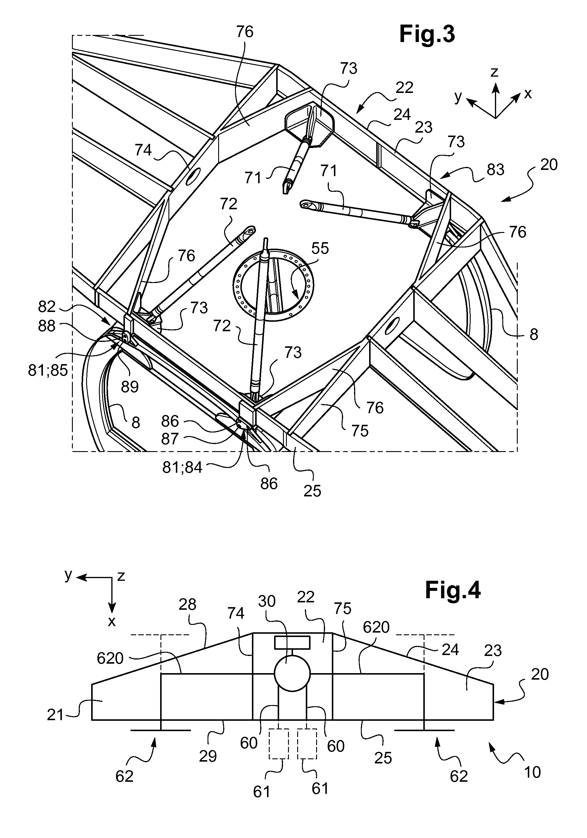
[0087]It should be observed that three mutually orthogonal directions x, y, and z are shown in some of the figures.

[0088]The first direction x is said to be longitudinal. The term “longitudinal” relates to any direction parallel to the first direction x.

[0089]The second direction y is said to be transverse. The term “transverse” relates to any direction parallel to the second direction y.

[0090]Finally, the third direction z is said to be in elevation. The term “in elevation” relates to any direction parallel to the third direction z.

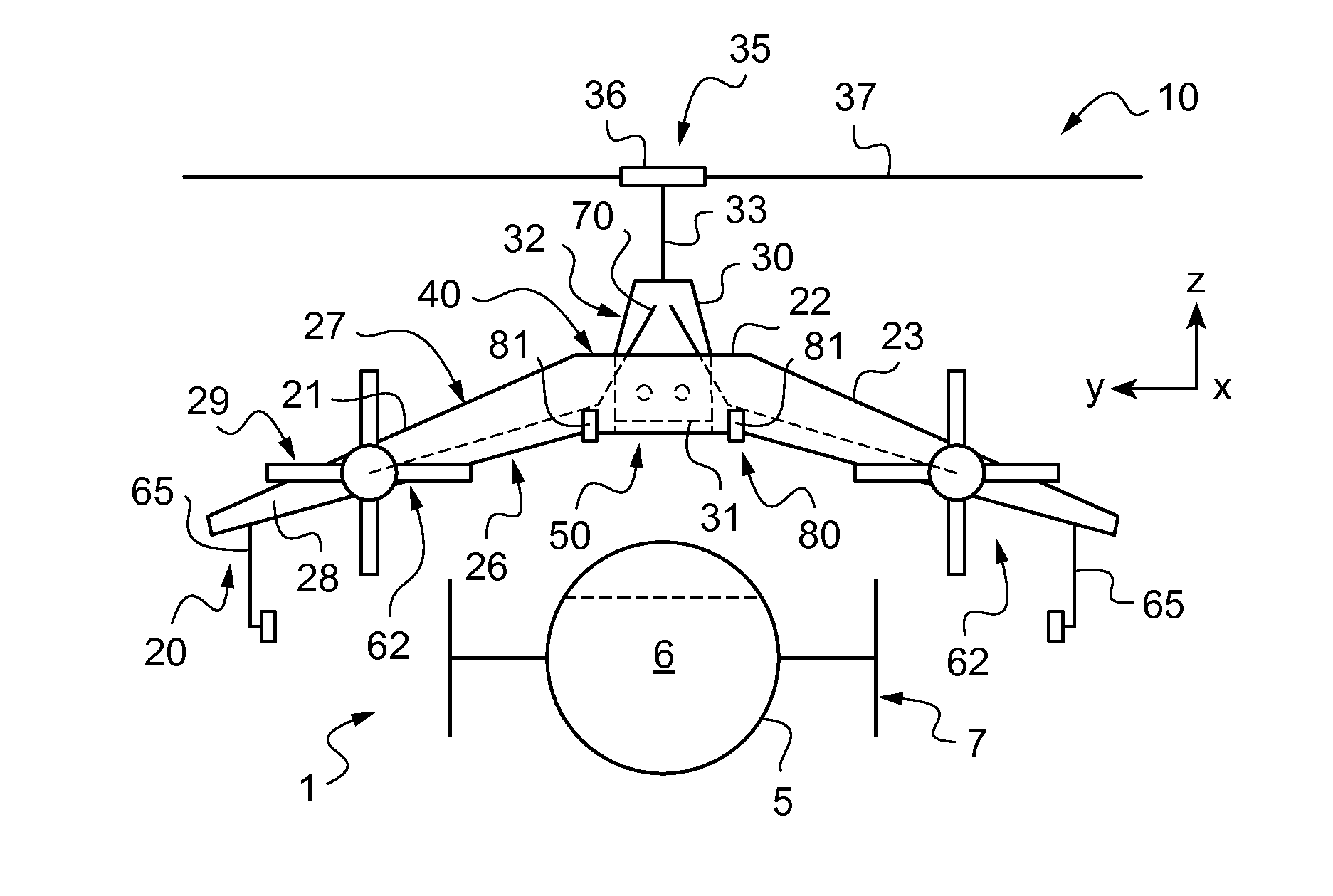
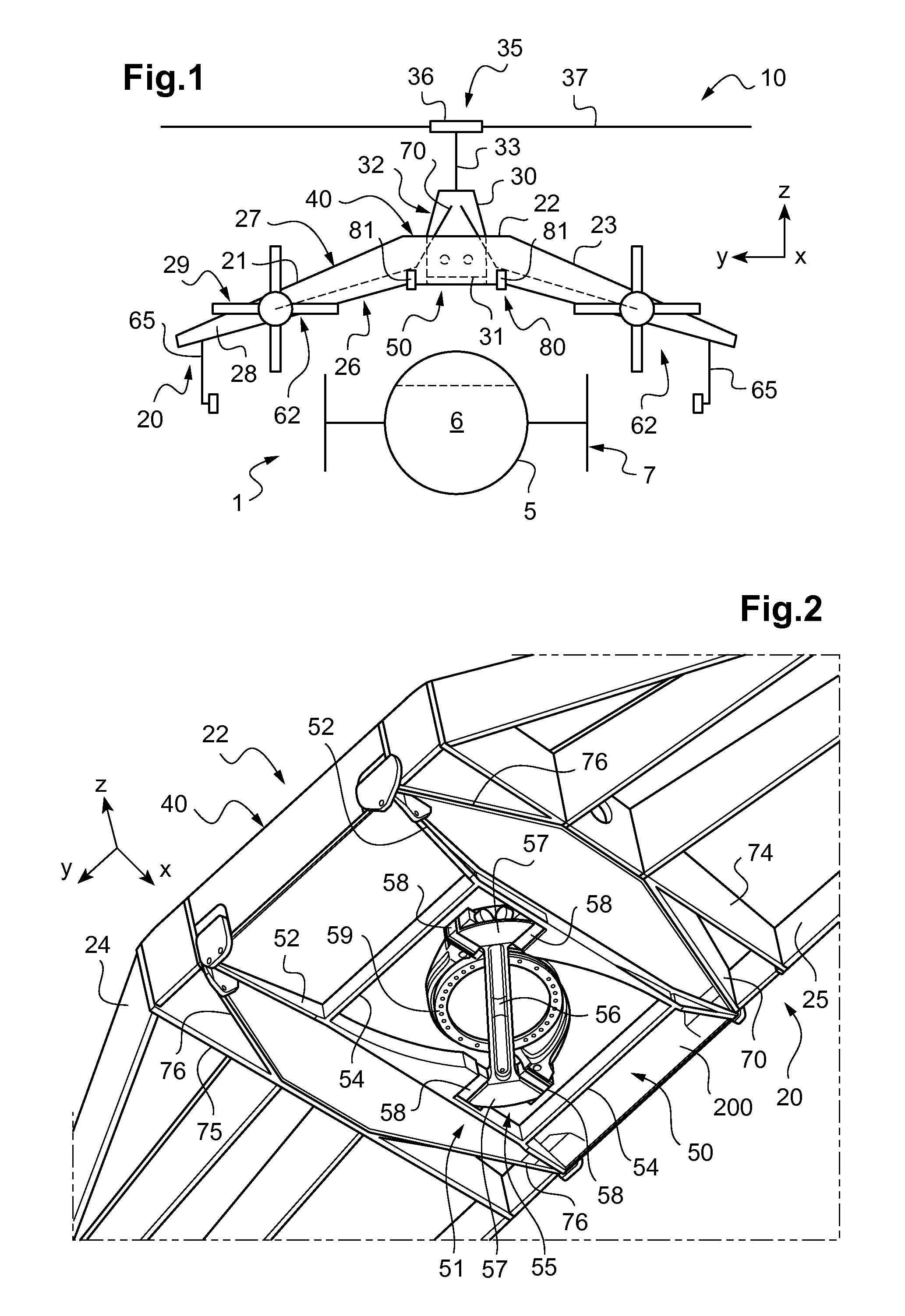
[0091]FIG. 1 shows an exploded view of a rotorcraft 1.

[0092]The rotorcraft 1 comprises a fuselage 5 extending longitudinally from a nose 6 to a tail end 7 carrying tail fins and / or stabilizers.

[0093]Furthermore, the rotorcraft 1 has a lift assembly 10 suitable for being reversibly fastened to the fuselage 5.

[0094]The lift assembly includes a wing and a rotor 35 capable of providing the rotorcraft 1 with at least part of its lift and / or propulsion. The wi...


PUM


Abstract

A lift assembly that is releasably fastened to a fuselage of a rotorcraft. The lift assembly comprises a wing comprising at least two spars. A main gearbox passes through an opening in the suction side of a central box of the wing so that its bottom is attached to a resilient suspension system arranged level with the pressure side of the central box, a top of the main gearbox projecting from the central box and being fastened to at least one spar by at least three suspension bars. A reversible fastener system having a plurality of fastener means serves to fasten the central box reversibly to a plurality of fastener points of a fuselage.

Description

CROSS REFERENCE TO RELATED APPLICATION[0001]This application claims priority to French patent application No. FR 14 00836 filed on Apr. 7, 2014, the disclosure of which is incorporated in its entirety by reference herein.BACKGROUND OF THE INVENTION[0002](1) Field of the Invention[0003]The present invention relates to a removable lift assembly for a rotorcraft and to a rotorcraft including such a lift assembly.[0004](2) Description of Related Art[0005]A rotorcraft has at least one rotor, sometimes referred to as its “main rotor”, that provides the rotorcraft with at least some of its lift, and possibly also with its propulsion.[0006]Such a main rotor may be set into rotation by a power plant comprising at least one engine and a main gearbox (mgb). The main gearbox is connected to a hub of the main rotor by a rotor mast and to at least one engine by a power drive train.[0007]The engine thus sets the main gearbox into motion and the main gearbox drives rotation of the main rotor.[0008]...

Claims


Application Information

Patent Timeline
IPC IPC(8): B64C27/26B64C27/32
CPCB64C27/26B64C2211/00B64C27/32B64C1/26B64C3/185
Inventor CACCIAGUERA, BRUNO
Owner EUROCOPTER
Learn More