Machine for spreading out and loading flat clothing articles

a flat clothing and machine technology, applied in the direction of stretching, washing apparatus, application, etc., can solve the problems of folds and wrinkles in flat clothing articles, and achieve the effects of reducing or eliminating, reducing the risk of injury, and good visibility

Active Publication Date: 2015-10-08
GIRBAU ROBOTICS
View PDF11 Cites 6 Cited by
  • Summary
  • Abstract
  • Description
  • Claims
  • Application Information

AI Technical Summary

Benefits of technology

[0037]In this embodiment of the machine with three loading stations, the aforementioned first and second access protection screens of the first and second loading stations, when they are in their closed positions, prevent the access of the first or second operator to the respective first and second pairs of loading clamps when the same are in the loading position, and the third loading station comprises a third access protection screen moved by driving means between an open position and a closed position. In the open position, said third access protection screen allows the access of the third operator to the corresponding pair of third loading clamps when the same is in the loading position, and in the closed position the third access protection screen prevents the access of the third operator to the corresponding pair of third loading clamps.
[0038]The three loading stations include respective first, second and third intermediate screens moved by driving means between a closed position and an open position. In the closed position, the first, second and third intermediate screens are interposed between the pairs of first, second and third loading clamps and the pairs of first and second spreading clamps when the latter are in the receiving position, such that they prevent the access of the corresponding first, second or third operator to the first and second pairs of spreading clamps when the corresponding first, second and third access protection screens are in their open position. In the open position, the first, second and third intermediate screens allow the movements of the pairs of first, second and third loading clamps between their loading and transferring positions.
[0039]In an embodiment, the movements of the loading clamps between their loading positions and their delivery positions are driven by driving means controlled by control means configured for stopping said driving means in the event that the loading clamps encounter a resistance above a predetermined threshold during their movements between the loading positions and the delivery positions. This eliminates or reduces to the minimum the risk of injury for the operator in the event that he / she puts his / her hands between the loading clamps and the spreading clamps. With this control system for controlling the movements of the loading clamps, the function of the access protection screens may be unnecessary, therefore the access protection screens can be omitted.
[0040]The first, second and third loading stations described above allow the machine of the present invention to function in a semiautomatic loading mode in which the corresponding operators manually load two contiguous corners of the flat clothing article to the clamps and the machine automatically performs the subsequent operations of spreading, positioning and depositing and transporting the flat clothing article. However, the machine of the present invention is prepared to function in a manual loading mode, in which one or more, generally up to three, operators can load small flat clothing articles directly on the loading end of the conveyor belt.
[0041]To that end, the protective cover is installed in a casing portion, which is in turn connected to the frame of the machine by a casing hinge. In the embodiment with two loading stations, the casing portion together with the protective cover can pivot with respect to the frame between a semiautomatic loading position and a manual loading position. In said semiautomatic loading position the protective cover frontally covers the loading end of the conveyor belt such that the large flat clothing articles can be loaded through the loading stations in the semiautomatic loading mode as has been described above. Contrarily, in said manual loading position the protective cover is lifted up and exposes the loading end of the conveyor belt such that it allows one or more operators to manually load small flat clothing articles directly on the loading end of the conveyor belt in the manual loading mode. In this manual loading position the protective cover is lifted up sufficiently to provide the operators with good visibility of the clothing articles deposited.
[0042]In the embodiment with three loading stations, the protective cover is also installed in the mentioned casing portion similarly to the embodiment with two loading stations, and the third loading station is directly connected to the casing portion. Thus, the casing portion pivots together with the protective cover and the third loading station between the semiautomatic loading position and the manual loading position. In the semiautomatic loading position, the protective cover and the third loading station are in an operative condition. In the manual loading position, the protective cover and the third loading station are in inoperative positions and are lifted up sufficiently to provide the operators with good visibility of the clothing articles deposited.

Problems solved by technology

One drawback of clamps of this type is the fact that the contiguous corners of the flat clothing article are transferred from the loading clamps to the spreading clamps in conditions which do not assure a correct attachment of the corners in the spreading clamps, and this causes folds and wrinkles in the flat clothing article when the same is subsequently deposited on the conveyor belt by the deposition means.
These machines for spreading and loading flat clothing articles of the state of the art have in general one or more of the following drawbacks:Risk for the operators due to the movements of the clamps which are necessarily fast if wanting to achieve a high productivity.Productivity relatively limited by the time taken by the conveyor belt to load a flat clothing article, since the spreading clamps cannot spread and position a flat clothing article until the loading end of the conveyor belt is free to receive it and to not hinder the preceding flat clothing article.Bad quality in depositing the flat clothing articles on the conveyor belt, for example the presence of folds and wrinkles due to the bad conditions in which the deposition is performed in machines of high productivity.Large sizes of the machine, for example in those cases in which the transferring means are located at a height sufficient to keep certain movable elements away from the operators and thus reducing their risk.Poor visibility of the small flat clothing articles deposited on the conveyor belt in the manual loading mode due to the concealment caused by protection elements partially removed for accessing the conveyor belt.

Method used


Image

  • Machine for spreading out and loading flat clothing articles
  • Machine for spreading out and loading flat clothing articles
  • Machine for spreading out and loading flat clothing articles

Examples


second embodiment

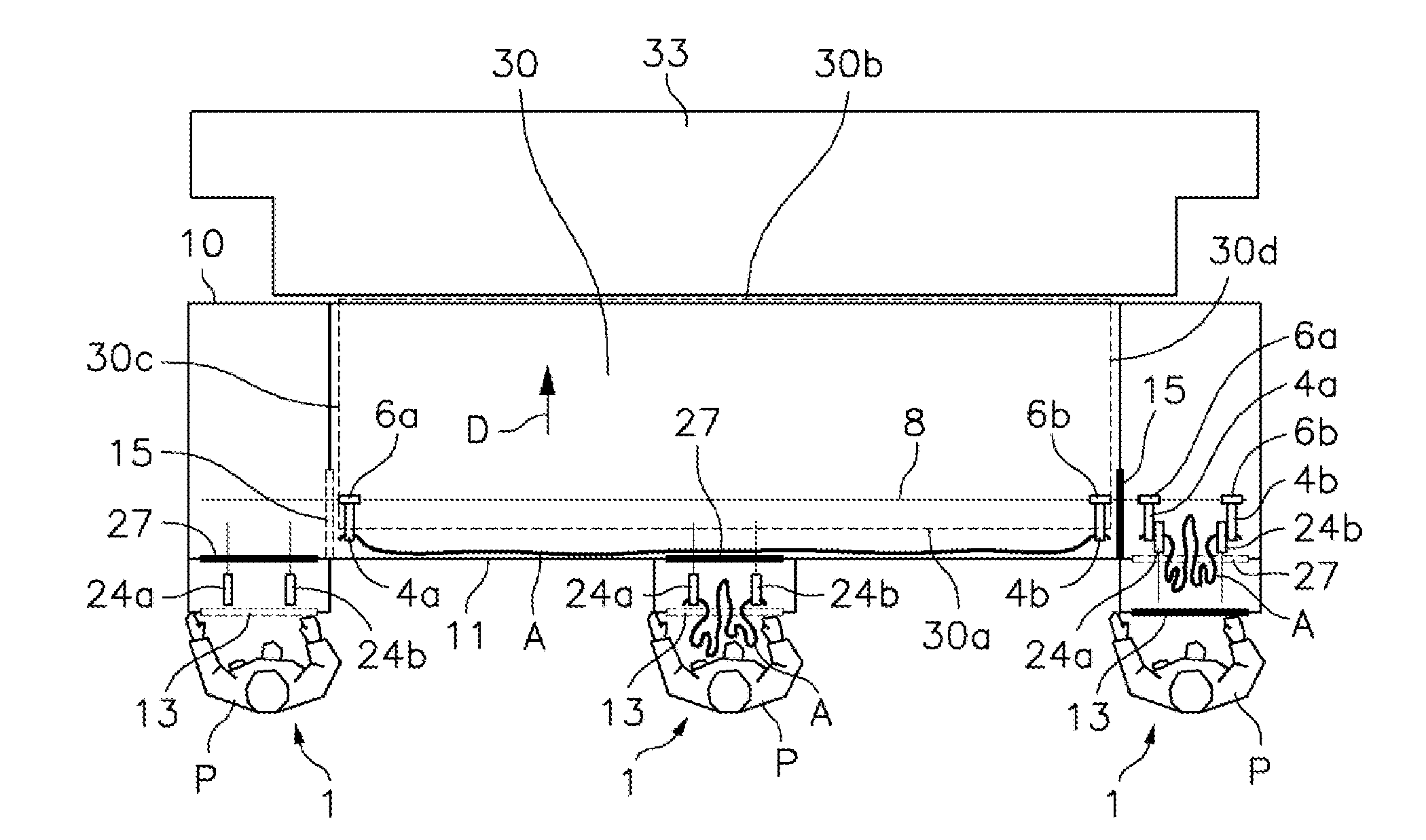
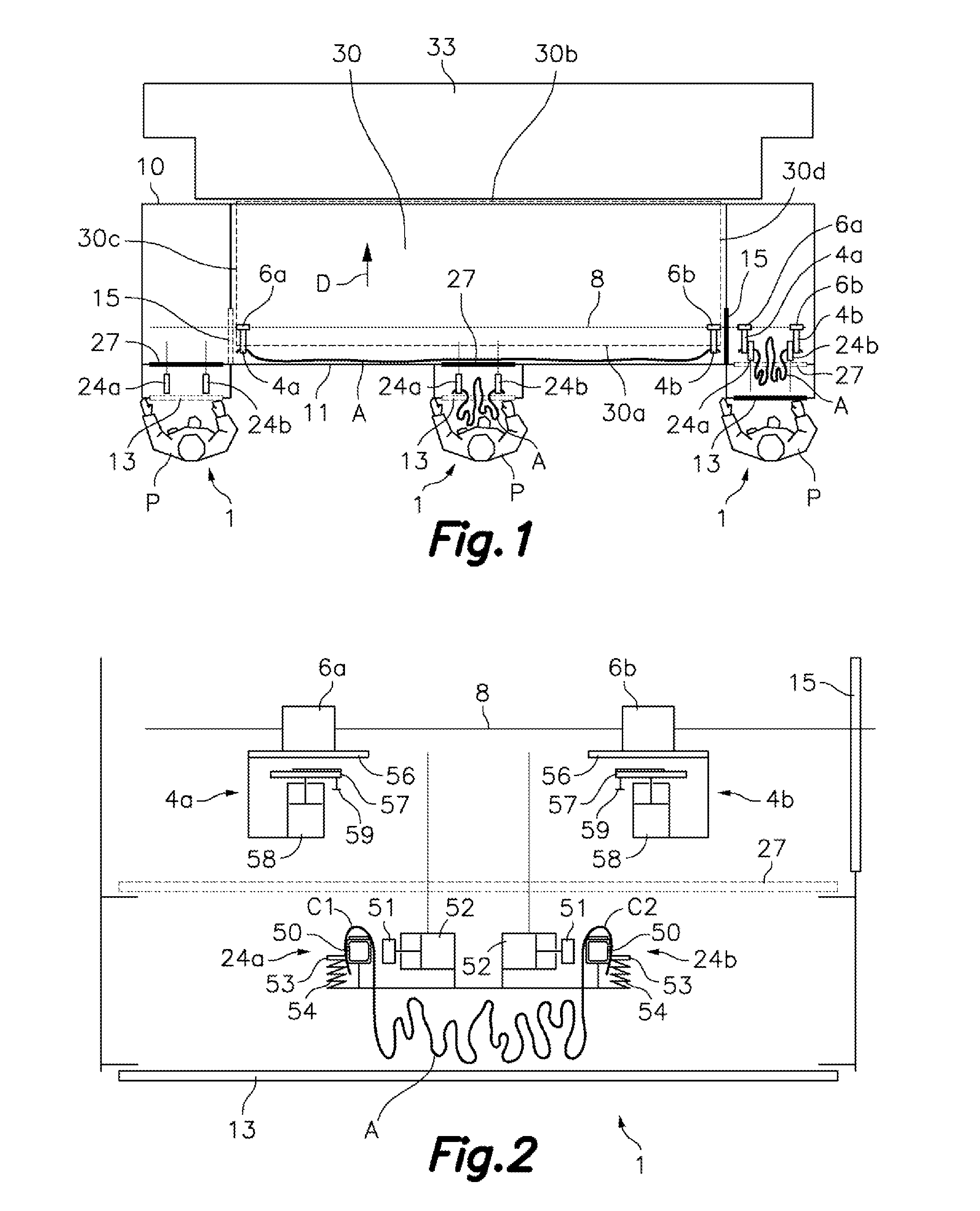
[0092]Referring now to FIGS. 13 to 19, there is shown a machine for spreading out and loading flat clothing articles according to the present invention, which comprises a frame 10 supporting a conveyor belt 30 having a considerably horizontal or slightly inclined upper section moving in a loading direction D. The conveyor belt 30 has a loading end 30a on which there is deposited a duly spread out and positioned upper part of flat clothing articles A1, A2, and an unloading end 30b, from which the spread out flat clothing articles A1, A2 are transferred to a laundry processing unit 33, such as an ironing unit or a folding unit, schematically depicted by means of dashed lines. Flat clothing articles are understood as linen elements and other clothing for use in the home, hospitals, hotels, restaurants, etc., such as tablecloths, napkins, sheets, pillowcases, and cloths, among others.

[0093]The mentioned loading end 30a of the conveyor belt 30 is covered frontally by a protective cover 1...

third embodiment

[0120]In the third embodiment with three loading stations 1, 2, 3, when the first and second access protection screens 13, 14 of the first and second loading stations 1, 2 are in the closed position, they prevent the access of the first and second operators P1, P2 to the respective pairs of first and second loading clamps 24a, 24b; 25a, 25b, and the third loading station 3 comprises a third access protection screen 31 moved by driving means between an open position, in which said third access protection screen 31 allows the access of the third operator P3 to the corresponding pair of third loading clamps 26a, 26b when the same is in the loading position, and a closed position, in which said third access protection screen 31 prevent the access of the third operator P3 to the corresponding pair of third loading clamps 26a, 26b.

[0121]Furthermore, the first, second and third loading stations 1, 2, 3 include respective first, second and third intermediate screens 27, 28, 29 moved by dri...


PUM

PropertyMeasurementUnit
distanceaaaaaaaaaa
distanceaaaaaaaaaa
distanceaaaaaaaaaa

Abstract

The machine comprises a conveyor belt (30) and loading clamps (24a) which receive contiguous corners (A1) of a flat clothing article (A) manually loaded by an operator (P) in a loading station (1) and transfer them to spreading clamps (4a). Each loading clamp (24a) has a loading jaw (51) driven by an actuator (52) and an auxiliary loading jaw (53) with yielding and recovery capacity to catch parts of the corner (A1) against opposite sides of a loading support (50), and an air blowing nozzle (55) producing an airflow capable of pushing a portion of corner (A1) released from the auxiliary loading jaw (53) and introducing it between jaws of a corresponding spreading clamp (4a) driven by an actuator (58) for catching the portion of corner (A1) previously released.

Description

TECHNICAL FIELD[0001]The present invention relates to a machine for spreading out and loading flat clothing articles such as sheets or tablecloths, useful for loading such articles to a laundry processing unit, such as an ironing machine, dryer or the like.BACKGROUND OF THE INVENTION[0002]Machines for spreading out and loading flat clothing articles comprising a frame supporting a conveyor belt and several loading stations served by respective operators in a semiautomatic loading mode are known in the prior art. Each loading station comprises a pair of loading clamps in which the corresponding operator secures two contiguous corners of a large flat clothing article, for example a sheet or a tablecloth. These loading clamps are moved from a loading position where the large flat clothing article has been loaded to a transferring position in which the loading clamps transfer the contiguous corners of the flat clothing article to spreading clamps. The spreading clamps are then moved in ...

Claims


Application Information

Patent Timeline
Patent Type & Authority Applications(United States)
IPC IPC(8): D06F67/04
CPCD06F67/04D06F71/38D06C3/00B65G47/04
Inventor GARRONE, DOMINIQUEDUPLOUY, SYLVAINGORRIZ, MANUEL
Owner GIRBAU ROBOTICS
Why Eureka
Try Eureka