Plate heat exchanger plate for a plate heat exchanger, a plate heat exchanger comprising such plates, a device for heating comprising the plate heat exchanger and a method for heat exchange

a technology of heat exchanger and plate, which is applied in the direction of heating type, stationary conduit assembly, combustion process, etc., can solve the problems of high carbon monoxide emissions, limited design options of compact burners and heat exchangers, and material destruction risk

Active Publication Date: 2015-10-08
HEATCORE
View PDF9 Cites 3 Cited by
  • Summary
  • Abstract
  • Description
  • Claims
  • Application Information

AI Technical Summary

Benefits of technology

[0014]The catalyst can be tapered, such as conical or formed as a half sphere or in any other suitable manner, so that the combustion takes place from the outside and into the burner. Further, the device can be arranged so that the combustion takes place from the top and downwards. Thereby, over-heating of the covers of the burner is avoided, which covers in addition are cooled by incoming fuel or mixture of fuel and air and also conductively by contact with the heat exchanger.

Problems solved by technology

The possibilities to design compact burners and heat exchangers are limited by the combustion technique in which a specific flame length is required to obtain efficient combustion.
Further, there is a risk that the flame per se or the flame zone come into direct contact with heat transfer surfaces of the heat exchanger, which will lead to high emissions of carbon monoxide and a risk of destruction of materials.
Hence, the result is that prior art devices are inefficient, space requiring, heavy and expensive.

Method used


Image

  • Plate heat exchanger plate for a plate heat exchanger, a plate heat exchanger comprising such plates, a device for heating comprising the plate heat exchanger and a method for heat exchange
  • Plate heat exchanger plate for a plate heat exchanger, a plate heat exchanger comprising such plates, a device for heating comprising the plate heat exchanger and a method for heat exchange
  • Plate heat exchanger plate for a plate heat exchanger, a plate heat exchanger comprising such plates, a device for heating comprising the plate heat exchanger and a method for heat exchange

Examples


Embodiment Construction

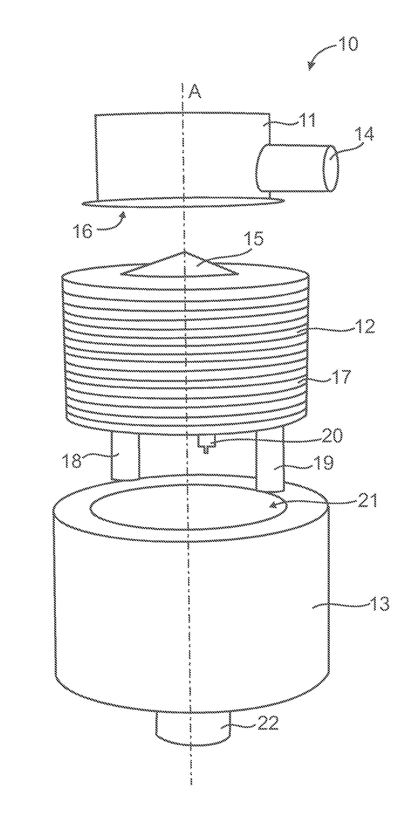
[0028]Referring to FIG. 1 a device 10 for heating according to one embodiment is illustrated schematically. The device 10 comprises a burner 11, a heat exchanger 12 and a shell 13 for containing the heat exchanger 12. For example, the heat exchanger 12 is a plate package of heat exchanger plates, wherein the plate package and the shell 13 form a plate and shell heat exchanger. For example, the device 10 is arranged for heating a medium, such as a liquid or a gas. For example, the device 10 is arranged for producing heat and hot water in buildings, such as dwelling houses, industry facilities, office buildings and similar. According to one embodiment the device 10 is mounted in a central heater, such as a wall-mounted heating boiler for production of heat and hot water.

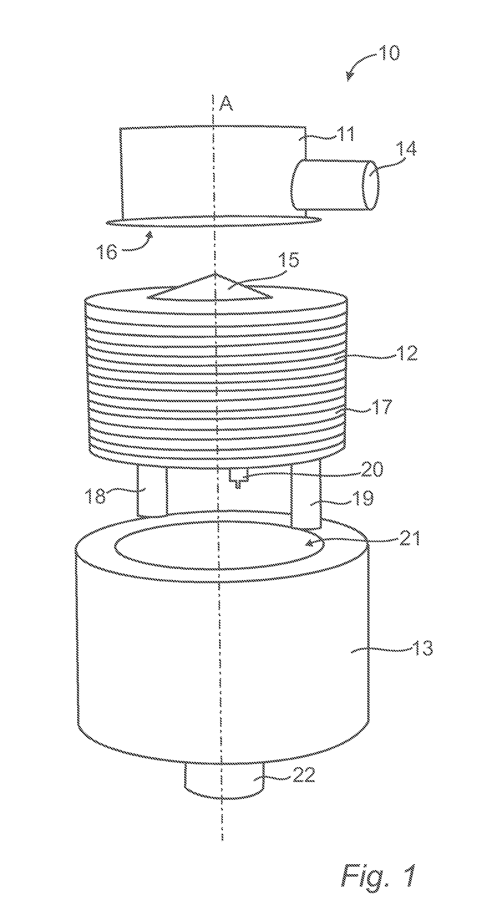
[0029]The burner 11 comprises an inlet 14 for conducting fuel, such as natural gas or any other suitable type of fuel, into the burner 11. For example, the inlet 14 is arranged for conducting a mixture of fuel and air ...


PUM


Abstract

A heat exchanger plate for a plate heat exchanger (12) includes a first side, a second side and a centre point (P) through which an imaginary centre axis (A) extends in a direction perpendicular to a plane of the plate. The plate comprises a first port for a first medium, and at least a second port and a third port for a second medium. The plate further comprises a first sealing arranged on the second side around the first port, a second sealing arranged on the second side at a circumference of the plate, and a closed third sealing arranged between the first and second sealings to form a first heat transfer area and a second heat transfer area separated from the first heat transfer area. The second port is arranged in the first heat transfer area and the third port is arranged in the second heat transfer area.

Description

FIELD OF THE INVENTION[0001]The present invention relates to a heat exchanger plate for a plate heat exchanger. Further, the invention relates to a plate heat exchanger comprising a plurality of such heat exchanger plates. Heat exchangers are used for transferring thermal energy from a first medium to a second medium, such as for recovering heat from the first medium. One type of heat exchangers comprises a plurality of heat exchanger plates in the form of a plate package arranged in a shell to form a so called plate and shell heat exchanger.[0002]The invention also relates to a device for heating, comprising a burner and a plate heat exchanger for recovering thermal energy from combustion gases produced by the burner. This type of devices for heating can be used in a central heater for heat and hot water production. The invention also relates to a method for heat exchange between a first medium and a second medium.PRIOR ART[0003]There are numerous different types of heat exchangers...

Claims


Application Information

Patent Timeline
Patent Type & Authority Applications(United States)
IPC IPC(8): F28D1/03
CPCF28D1/0333F23C5/08F23C13/00F23D14/00F24H1/32F23C3/00F23C7/00F23C2900/13001F23D14/02F23D14/66F23D2900/00003F24D3/08F24H1/0045F24H1/38F24H1/43F24H1/48F28D9/0012F28D9/0043F28D21/0007F28F3/086Y02E20/34F23C5/02F23C9/00
Inventor SILVERSAND, FREDRIK
Owner HEATCORE
Why Eureka
Try Eureka