Emotion recognition in video conferencing

a video conferencing and emotion recognition technology, applied in the field of video conferencing, can solve the problems of difficult task even for experienced professionals, difficult to spot customer anger, and difficult to deal with angry, annoyed and distressed customers

Active Publication Date: 2015-10-08
SNAP INC
View PDF8 Cites 100 Cited by
  • Summary
  • Abstract
  • Description
  • Claims
  • Application Information

AI Technical Summary

Benefits of technology

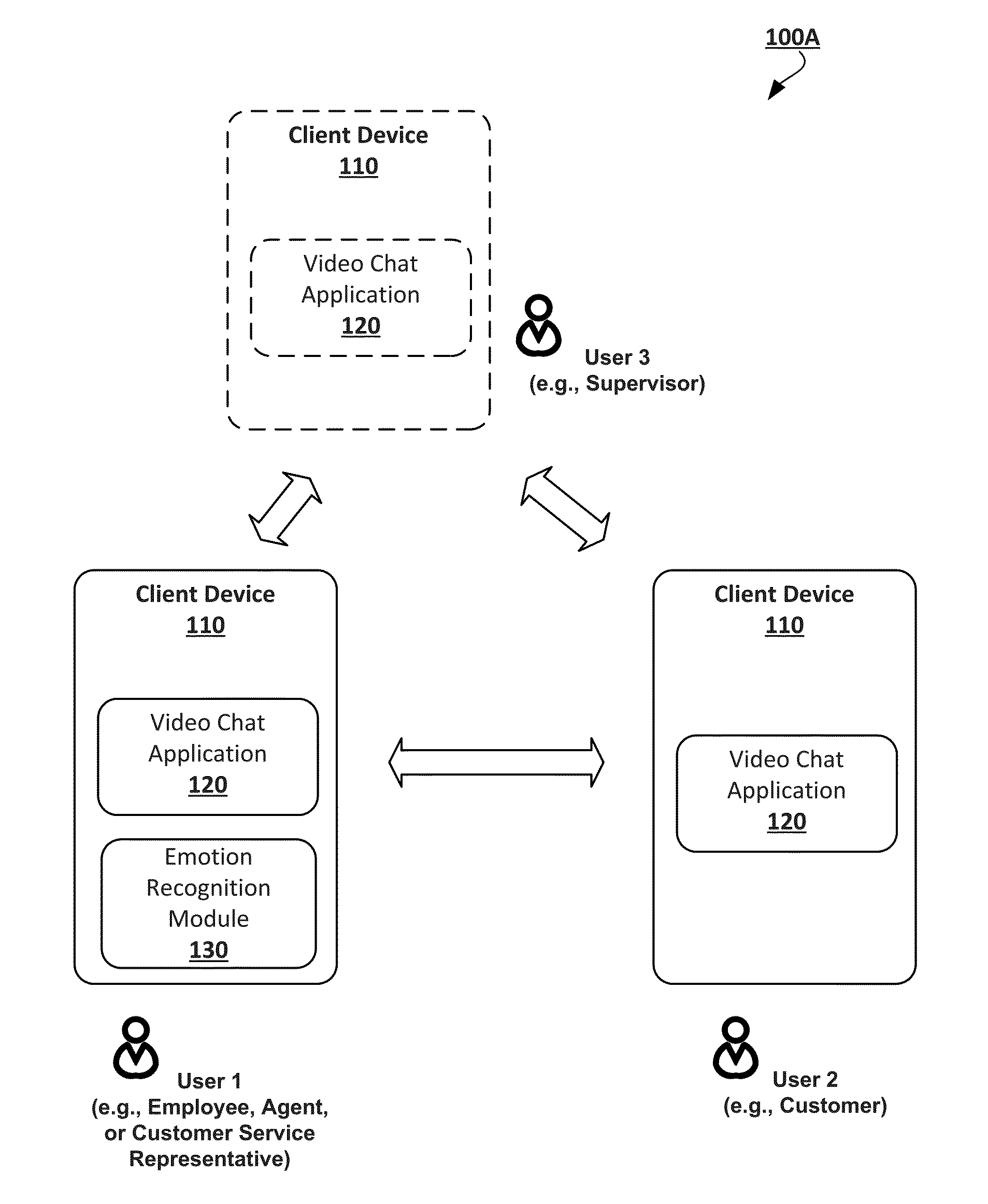
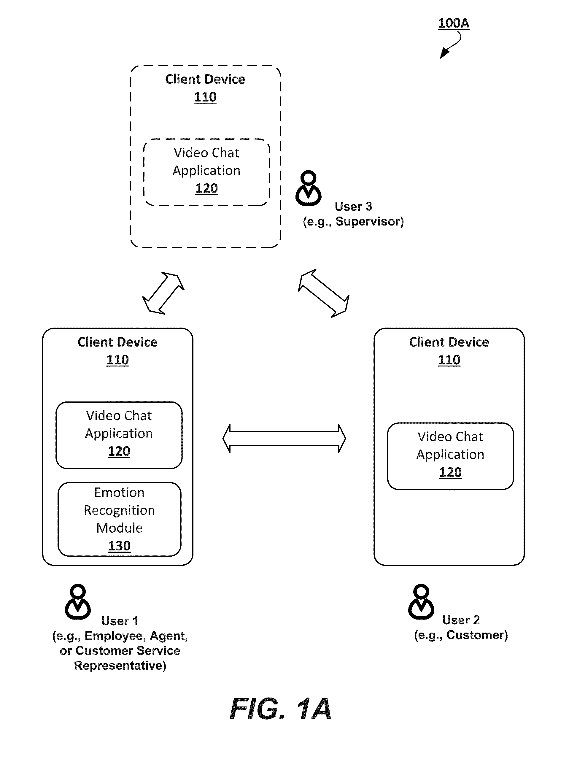
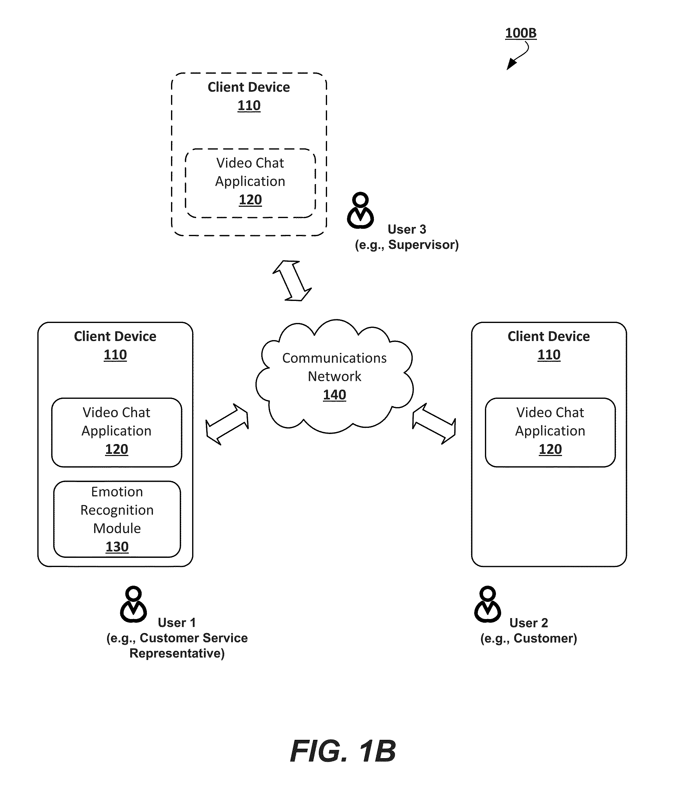
[0005]This disclosure relates generally to the technology for video conferencing, in which an emotional status of participating individuals can be recognized. The videoconferencing may include two or more participants including, for example, a customer and a customer service representative. If the recognized emotional status relates to a negative emotion, such as anger, stress, irritation, and annoyance, the emotional status can be reported to one of the videoconference participants and / or a third party such as a supervisor, administrator, or manager. Optionally, the third party can enter into the videoconference between the individuals to resolve any issues. The technology allows determining the emotional status by analyzing a video channel to detect facial emotions and / or an audio channel to detect speech emotions. The present technology can recognize facial emotions by locating feature reference points (e.g., facial landmarks) on the video, aligning a virtual face mesh to the feature reference points, and finding mesh deformations that reflect face mimics. Speech emotions can be recognized by extracting voice features and determining changes thereof.

Problems solved by technology

Although videoconferencing creates a useful channel to provide services to customers, one challenging issue is to deal with irate, annoyed and distressed customers.
Customer anger is not always easy to spot even to professional service providers or sale representatives.
Unfortunately, it is a very difficult task even to experienced professionals.

Method used


Image

  • Emotion recognition in video conferencing
  • Emotion recognition in video conferencing
  • Emotion recognition in video conferencing

Examples


Embodiment Construction

[0031]The following detailed description includes references to the accompanying drawings, which form a part of the detailed description. The drawings show illustrations in accordance with example embodiments. These example embodiments, which are also referred to herein as “examples,” are described in enough detail to enable those skilled in the art to practice the present subject matter.

[0032]The embodiments can be combined, other embodiments can be utilized, or structural, logical and operational changes can be made without departing from the scope of what is claimed. The following detailed description is, therefore, not to be taken in a limiting sense, and the scope is defined by the appended claims and their equivalents.

[0033]Present teachings may be implemented using a variety of technologies. For example, the methods described herein may be implemented in software executing on a computer system or in hardware utilizing either a combination of microprocessors or other specially...


PUM


Abstract

Methods and systems for videoconferencing include recognition of emotions related to one videoconference participant such as a customer. This ultimately enables another videoconference participant, such as a service provider or supervisor, to handle angry, annoyed, or distressed customers. One example method includes the steps of receiving a video that includes a sequence of images, detecting at least one object of interest (e.g., a face), locating feature reference points of the at least one object of interest, aligning a virtual face mesh to the at least one object of interest based on the feature reference points, finding over the sequence of images at least one deformation of the virtual face mesh that reflect face mimics, determining that the at least one deformation refers to a facial emotion selected from a plurality of reference facial emotions, and generating a communication bearing data associated with the facial emotion.

Description

TECHNICAL FIELD[0001]This disclosure relates generally to video conferencing and, more particularly, to systems and methods for recognizing emotions of participants in video conferencing.DESCRIPTION OF RELATED ART[0002]Today, video conferencing and videophone calls are popular tools for conducting two-way video and audio communications over long distances. This technology has been developing rapidly due to the emergence of high speed networking solutions, inexpensive hardware components, and deployment of cellular networks. Typically, video conferencing allows two or more individuals to communicate with each other using a variety of software applications, such as video chat applications, where the participants can view each other while talking. Video chats can be available on general-purpose computers, mobile devices, and television systems as downloadable software applications or web services. Traditional hardware requirements for video conferencing include, on each side, an input ...

Claims


Application Information

Patent Timeline
Patent Type & Authority Applications(United States)
IPC IPC(8): G06K9/00H04N7/15G10L25/63
CPCG06K9/00315G10L25/63H04N7/15G06K9/00281G06K9/00261H04N7/147G10L25/57G06Q30/0281G06V40/165G06V40/176G06V10/7553G06T7/344G06T2207/30201G06V40/167G06V20/64G06V40/171G06T7/337G06T2207/10016
Inventor SHABUROV, VICTORMONASTYRSHIN, YURII
Owner SNAP INC
Why Eureka
Try Eureka