Battery temperature control device

a temperature control device and battery technology, applied in the direction of battery/fuel cell control arrangement, cell components, battery/short circuit electrodes, etc., can solve the problems of condensed water having difficulty in reaching the battery electrode, short circuit electrodes,

Active Publication Date: 2015-10-15
NISSAN MOTOR CO LTD
View PDF8 Cites 35 Cited by
  • Summary
  • Abstract
  • Description
  • Claims
  • Application Information

AI Technical Summary

Benefits of technology

[0012]Consequently, the condensed water generated at the evaporator of the t

Problems solved by technology

However, in the conventional battery cooling system, when a drainage is provided, foreign objects such as water, dust, mud, and the like are received by the waste water drain which can reach a battery electrode, causing the problem of short circuiting electrode

Method used


Image

  • Battery temperature control device
  • Battery temperature control device
  • Battery temperature control device

Examples


first embodiment

[0024]First, a description is given of the configuration.

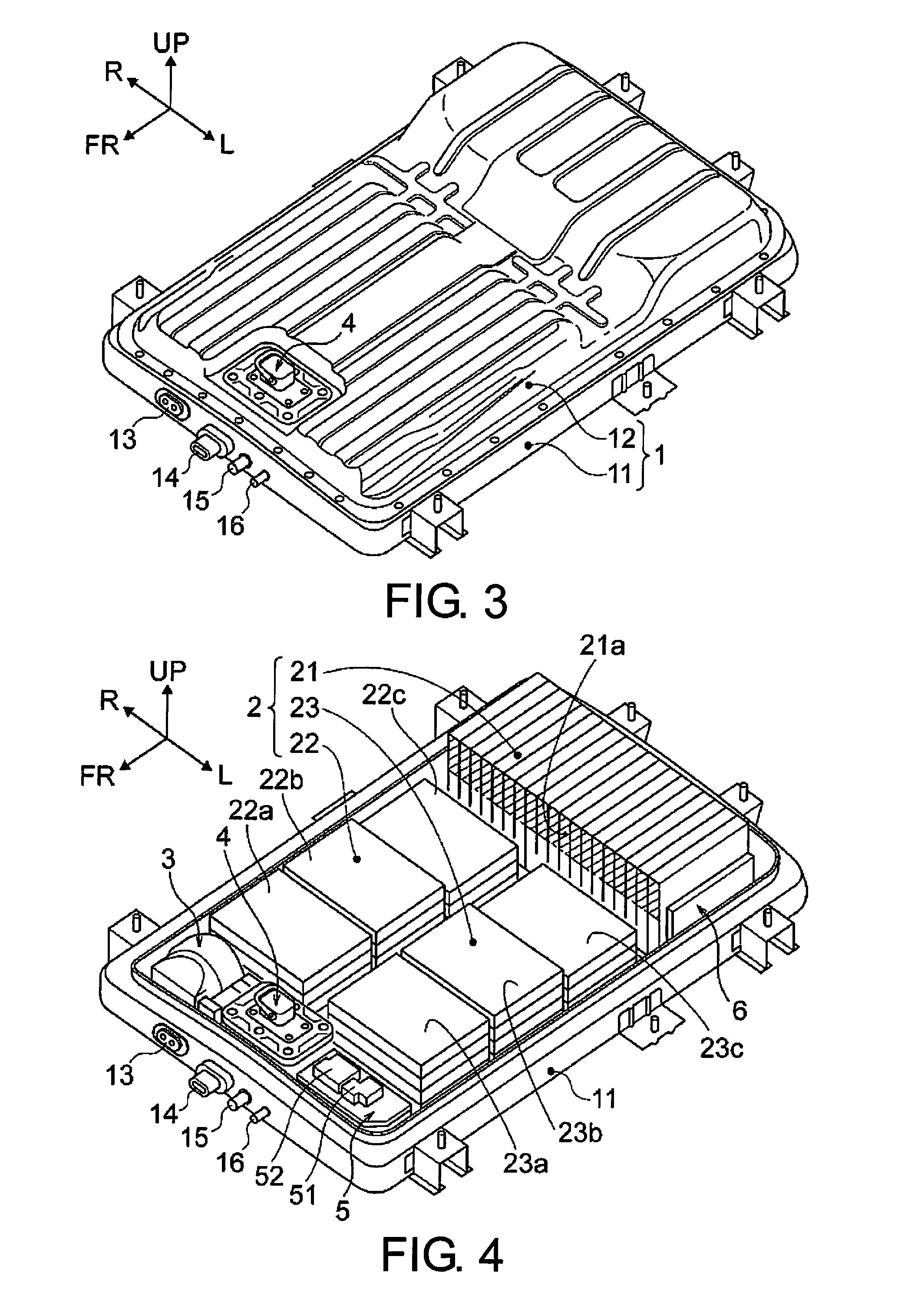
[0025]The structure of the battery temperature control device is separately described in “VEHICLE MOUNTING STRUCTURE OF BATTERY PACK BP”, “OVERALL DETAILED STRUCTURE OF BATTERY PACK BP”, “REGION-PARTITIONING CONFIGURATION FOR CASE INTERNAL SPACE”, and “DETAILED STRUCTURE OF BATTERY TEMPERATURE CONTROL DEVICE”, respectively.

Vehicle Mounting Structure of Battery Pack BP

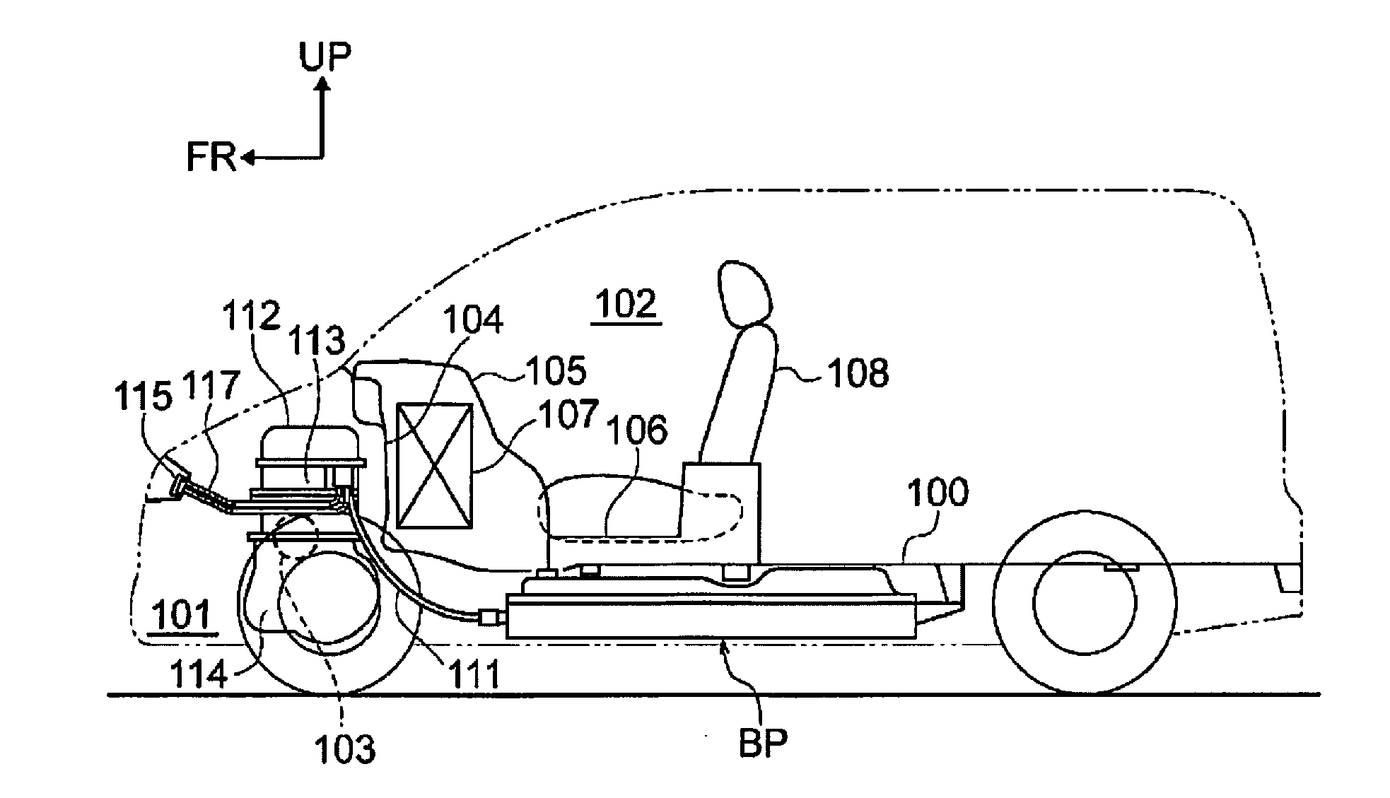
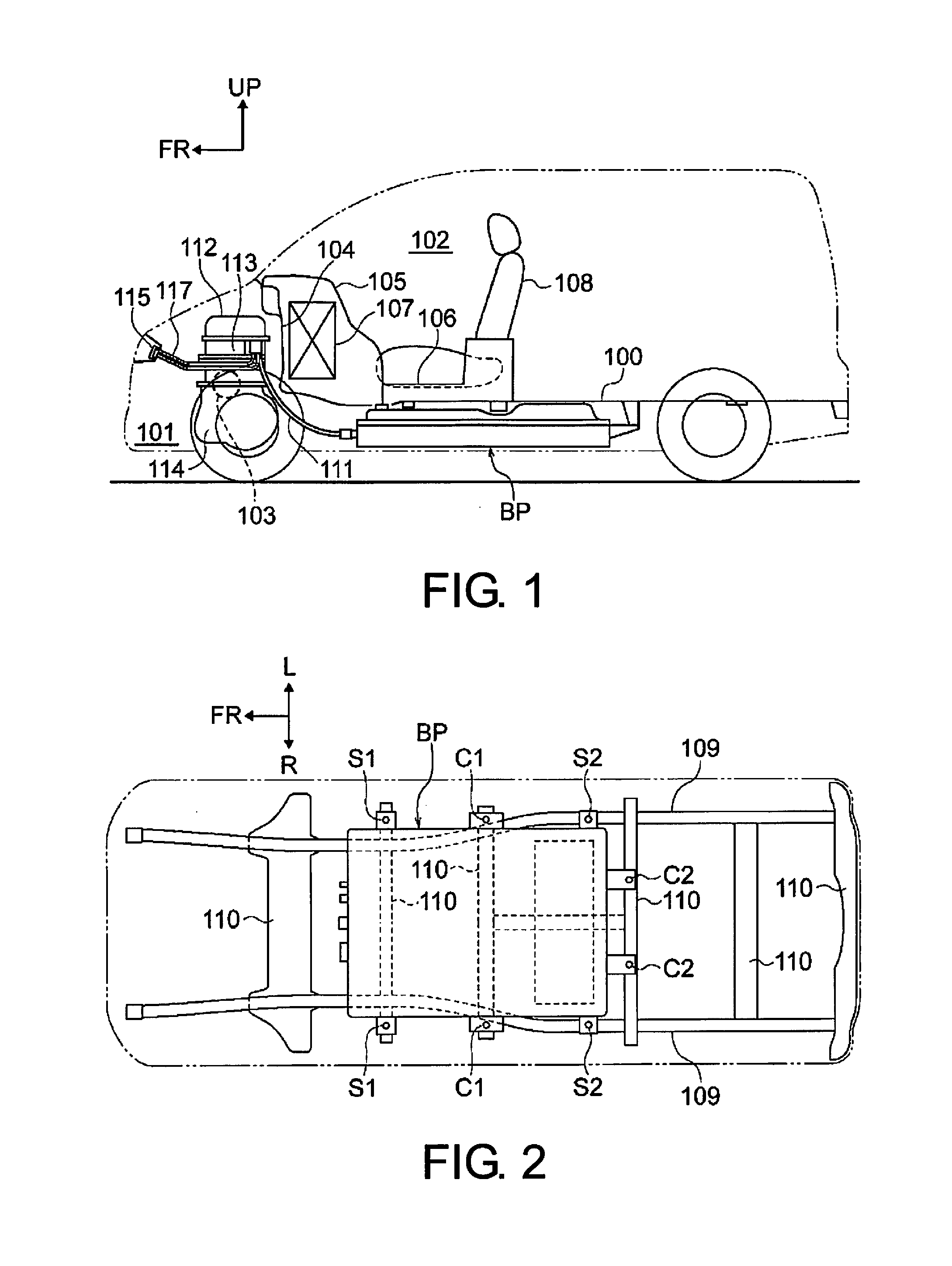
[0026]FIGS. 1 and 2 illustrate an electric vehicle on which a battery pack BP adopting a battery temperature control device in a first embodiment. Below, with reference to FIGS. 1 and 2, a description is given of the structure of the vehicle battery pack BP.

[0027]As shown in FIG. 1, the battery pack BP is placed under a floor panel 100 somewhere in the middle of the wheelbase. The floor panel 100 is structured to extend from a position connected to a dash panel 104, by which a motor room 101 and a vehicle passenger compartment 102 are separated, to a position of t...


PUM


Abstract

A battery temperature control device has a battery pack case that houses a temperature control unit and a battery stack as a group of battery modules. The temperature control unit has an evaporator exchanges heat using the air conditioning unit from the upstream side of the direction of airflow, a blower fan that recirculates the interior air inside the pack case, a PTC heater as a fin member, and a unit duct that supplies air to the battery stack.

Description

CROSS-REFERENCE TO RELATED APPLICATIONS[0001]This application is a U.S. National stage application of International Application No. PCT / JP2013 / 078455, filed Oct. 21, 2013, which claims priority to JP Patent Application No. 2012-243400 filed on Nov. 5, 2012, the contents of each of which are hereby incorporated herein by reference.BACKGROUND[0002]1. Field of the Invention[0003]The present invention relates to a battery temperature control device for battery modules housed in a battery pack case.[0004]2. Background Information[0005]Conventionally, a vehicle battery cooling system is known which discloses a structure in which, in order to drain the condensed water or condensate generated in the evaporator is tilted and a drainage is provided (for example, see Japanese Patent Application Publication No. 2008-54379 A).SUMMARY[0006]However, in the conventional battery cooling system, when a drainage is provided, foreign objects such as water, dust, mud, and the like are received by the wa...

Claims


Application Information

Patent Timeline
IPC IPC(8): B60K11/06B60L11/18H01M10/6563H01M10/625H01M10/613H01M10/6551B60H1/00H01M10/663B60L50/64
CPCB60K11/06B60H1/00278B60L11/1874H01M10/663H01M2220/20H01M10/613H01M10/6551H01M10/6563B60H2001/003H01M10/625B60L50/64H01M50/249B60L3/00B60H1/32H01M10/647H01M10/615H01M10/6571H01M10/6565B60K1/04B60K2001/005B60K2001/008B60K2001/0438B60L1/003B60L1/02B60L2240/34B60L2240/545B60L58/26B60L50/66B60L58/24B60L50/60Y02T10/70Y02E60/10
Inventor HATTA, KENTAROOSHIMA, KENTAROYANG, QIYE
Owner NISSAN MOTOR CO LTD
Why Eureka
Try Eureka