Inkjet ink composition

Active Publication Date: 2015-10-15
DOMINO PRINTING SCIENCES
View PDF16 Cites 11 Cited by
  • Summary
  • Abstract
  • Description
  • Claims
  • Application Information

AI Technical Summary

Benefits of technology

[0049]To achieve high quality codes, it is important that the ink can provide a long decap time so that high quality codes can be printed after periods of printer inactivity. In addition, thermal inkjet compositions for industrial marking and coding should exhibit short drying times on semi-porous or non-porous substrates, good adhesion on semi-porous or non-porous substrates and compatibility with the components of a thermal inkjet printer cartridge.
[0050]To improve adhesion onto non-porous substrates, it is known to add binders to the inkjet ink composition. However it is well known that the addition of binders can substantially reduce decap time. Terpene phenolic resins are known in the art to act as tackifiers to improve adhesion on to non-porous substrates. However intuitively one would also expect the addition of terpene phenolic resins to adversely affect decap time. It was therefore a surprise to the inventors to find that although a minor improvement in adhesion was achieved on addition of the terpene phenolic resin, a substantial improvement in decap time was observed.
[0051]The term “decap control,” as referred to herein, means the ability of the inkjet ink to readily eject from the print head, upon prolonged exposure to air. The ink decap time is measured as the amount of time that an inkjet printhead may be left uncapped before the printer nozzles no longer fire properly, potentially because of clogging or plugging. Generally, nozzle(s) may become clogged (i.e. impeded, slowed) or plugged (i.e. obstructed, substantially

Problems solved by technology

Some inkjet inks suffer from the ink drying out around the nozzles resulting in poor decap behaviour and therefore a loss of print quality.
Poor decap behaviour is often caused by the solvent in the ink evaporating and leaving behind non-volatile materials which at least partially obstruct the nozzles and are

Method used


Image

  • Inkjet ink composition
  • Inkjet ink composition

Examples


Example

Example 1

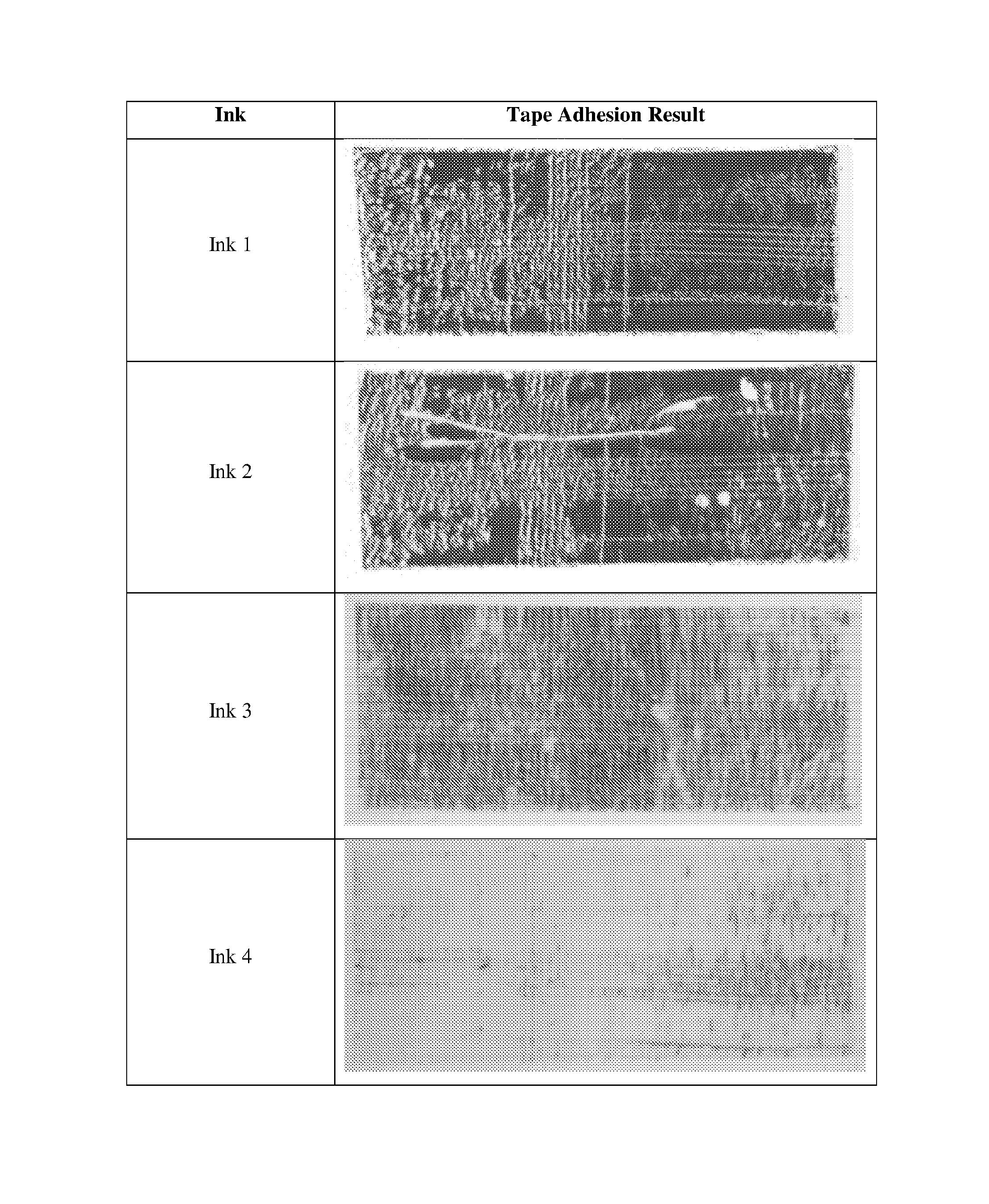
[0087]A set of Thermal inkjet inks suitable for printing onto semi-porous and non-porous substrates were prepared using the formulations shown in Table 1.

TABLE 1Ink 1(Control)Ink 2ComparativeComparativeComponentExampleExampleInk 3Ink 4Ethanol / %34.033.532.532.0Propyleneglycol49.549.549.549.5monomethyl ether / %1,1,2,2-11.411.411.411.4Tetramethoxyethane / %Surfactant / %0.10.10.10.1Acrylic binder / %—0.5—0.5Dertophene T / %——1.51.5Dye / %5.05.05.05.0

[0088]The percentages (%) are percentages (%) by weight based on the total weight of the composition.

[0089]The acrylic binder used was a methacrylate copolymer. The dye was solvent black 27. The surfactant was BYK-333, a Polyether-modified polydimethylsiloxane.

[0090]To assess the decap performance thermal inkjet cartridges were filled with each ink and 2D datamatrix codes were printed at 600×200 dpi. Each cartridge was then left with the nozzles exposed to the air for predetermined periods of time without printing or spitting the nozzles. Aft...

Example

Example 2

[0096]A further example of a thermal inkjet ink suitable for printing onto semi-porous and non-porous substrates was prepared using the formulations shown in Table 5.

TABLE 5ComponentInk 5Ethanol / %43.9Propyleneglycol monomethyl ether / %37.11,1,2,2-Tetramethoxyethane / %11.4Surfactant / %0.6Acrylic binder / %0.5Dertophene T / %1.5Dye / %5

[0097]The acrylic binder was a methacrylate copolymer. The dye was solvent black 27. The surfactant used was a combination of BYK-333 and Tego Glide 440, a polyether siloxane copolymer.

[0098]Decap measurements for Ink 5 were carried out using the method described above for the Example 1. The results are provided below in Table 6.

TABLE 62D Datamatrix Grade After Decap PeriodInk15 seconds1 minutes2 hours16 hours5CBBB

[0099]While a specific embodiment has been described in detail above, it will be apparent to those skilled in the art that the disclosed embodiment may be modified using different ink formulations in alternative Thermal Inkjet printing heads.


PUM

PropertyMeasurementUnit
Fractionaaaaaaaaaa
Fractionaaaaaaaaaa
Fractionaaaaaaaaaa

Abstract

An inkjet ink composition including one or more volatile organic solvents and one or more colorants, said ink being characterised in that it includes one or more humectants and a terpene phenolic resin.

Description

FIELD OF THE INVENTION[0001]This invention relates to inkjet ink compositions and in particular, though not necessarily solely, to compositions for thermal inkjet (TIJ) printing.BACKGROUND OF THE INVENTION[0002]In the field of industrial coding and marking codes, dating, and traceability information are applied directly onto products and / or product packaging. To achieve high quality images on a consistent basis in industrial environments, it is advantageous for the inkjet ink to have a long decap time.[0003]Decap time is defined as the period of time that a printhead can be left uncapped at idle and still produce a high quality code when printing is restarted. Some inkjet inks suffer from the ink drying out around the nozzles resulting in poor decap behaviour and therefore a loss of print quality. Poor decap behaviour is often caused by the solvent in the ink evaporating and leaving behind non-volatile materials which at least partially obstruct the nozzles and are therefore detrime...

Claims


Application Information

Patent Timeline
IPC IPC(8): C09D11/03C09D11/36C09D11/107
CPCC09D11/03C09D11/36C09D11/107
Inventor CROSS, JULIECHAM, CINDYPLAIS, FLORIE CLAUDINE
Owner DOMINO PRINTING SCIENCES
Why Eureka
Try Eureka