Power generator

a power generator and generator technology, applied in piezoelectric/electrostrictive/magnetostrictive devices, piezoelectric/electrostriction/magnetostriction machines, electrical apparatus, etc., can solve the problems of limiting the frequency range for which power can be generated, not being able to effectively obtain power, and not being able to generate sufficient deformation of spring members, etc., to achieve stable vibration displacement, improve the conversion efficiency of vibration energy, and simple structur

Active Publication Date: 2015-10-15
SUMITOMO RIKO CO LTD +1
View PDF16 Cites 16 Cited by
  • Summary
  • Abstract
  • Description
  • Claims
  • Application Information

AI Technical Summary

Benefits of technology

[0084]Because of that, oscillation of the first mass member 54 and the second mass member 32 during vibration input is inhibited, and as a result of more stable vibration displacement in the vertical direction which is the target main vibration input direction, the elastic deformation volume of the connecting rubber elastic body 22 and the plate spring 34 becomes large, and there is further improvement of the conversion efficiency from vibration energy to electrical energy.
[0085]In fact, the arrangement area of the second vibration system 16 is cut off from the external space by the first mass member 54, so it is possible to give dust proof properties and water proof properties with a simple structure for the arrangement area of the second vibration system 16 without requiring a separate cover structure or the like.
[0086]In addition, by the first mass member 54 having a hollow structure, while ensuring a large mass weight with the large capacity outer circumference part, it is possible to house the second vibration system 16 in the housing space 56, and to avoid large projection upward from the first mass member 54 as with the aforementioned embodiment. As a result, while ensuring sufficient mass of the first mass member 54, it is possible to suppress the height direction size of the overall vibration damping device to be small.

Problems solved by technology

However, with the power generator described in JP-A-2011-152004, the piezoelectric vibrating body is a one-degree-of-freedom vibration system for which the mass member is elastically supported by the spring member, so for vibration input of a frequency that is off from the natural frequency, there is the risk of not being able to generate sufficient deformation of the spring member, and not being able to effectively obtain power.
However, even with a structure for which a plurality of piezoelectric vibrating bodies is provided in this way, there is a limit to the frequency range for which power can be generated for each of the piezoelectric vibrating bodies, so it was difficult to make it possible to generate electricity for vibration input with a broad frequency range.

Method used


Image

  • Power generator
  • Power generator
  • Power generator

Examples


Embodiment Construction

[0045]Following, we will describe embodiments of the present invention while referring to the drawings.

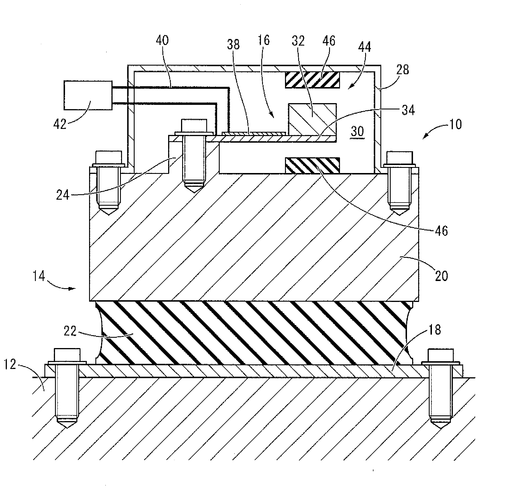
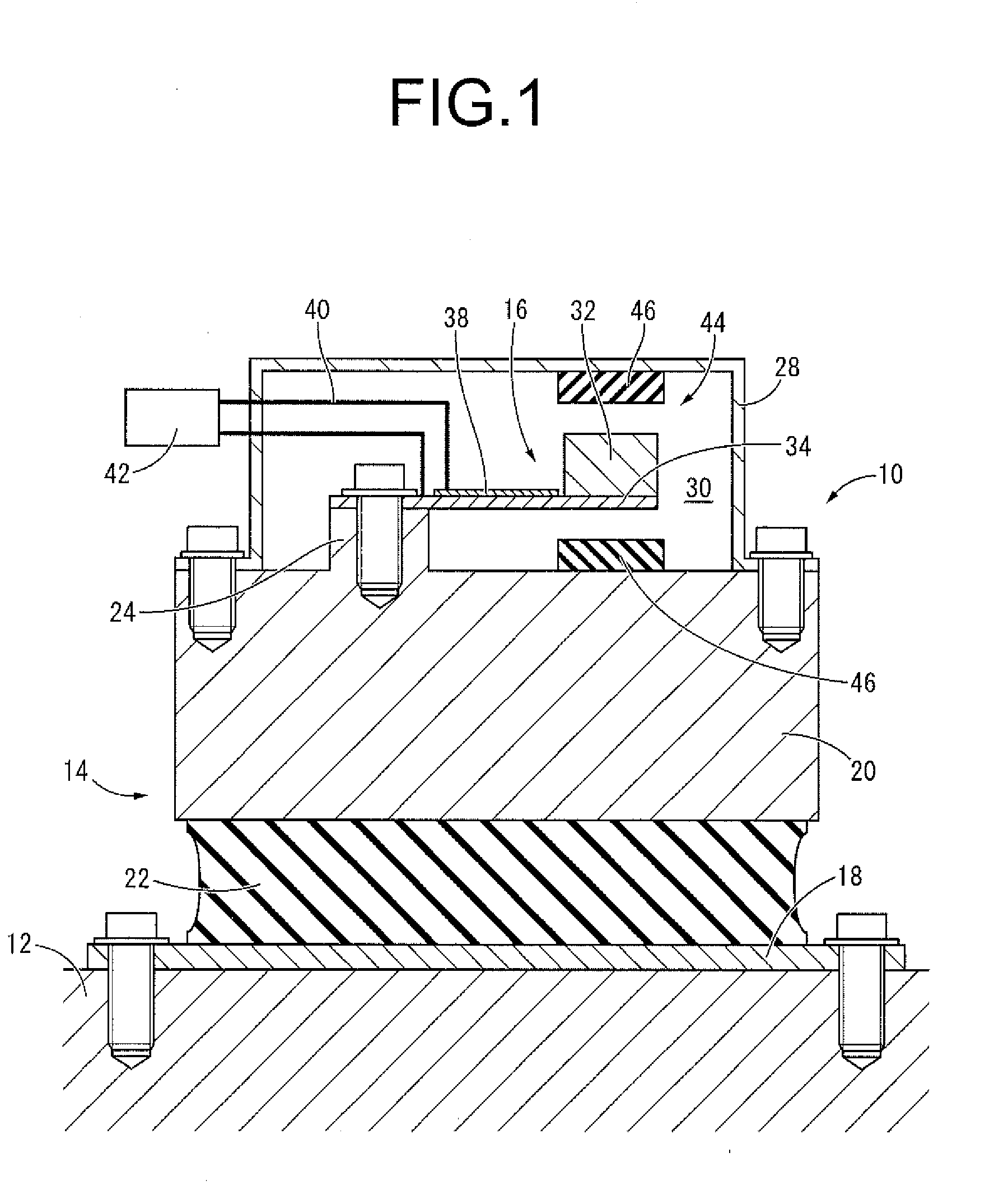
[0046]FIG. 1 shows a power generator 10 as a first embodiment of the present invention. As is also shown with the vibration model of FIG. 2, the power generator 10 is equipped with a multiple-degree-of-freedom vibration system including a first vibration system 14 attached to a body 12 as a vibrating member, and a second vibration system 16 attached to the body 12 via the first vibration system 14. With the description hereafter, unless there is a specific explanation, the vertical direction means the vertical direction in FIG. 1 which is the main vibration input direction of the body 12.

[0047]In more specific detail, the first vibration system 14 has a constitution for which an attachment member 18 and a first mass member 20 are elastically connected by a connecting rubber elastic body 22 as a first spring member, and by the attachment member 18 being fixed to the body 12 by a bol...


PUM


Abstract

A power generator including: a vibration system configured to be attached to a vibrating member; and a power generating element attached to the vibration system. The vibration system is a multiple-degree-of-freedom vibration system that includes a first vibration system having a first mass member elastically supported by a first spring member, and a second vibration system having a second mass member elastically connected to the first mass member by a second spring member. The power generating element is arranged between the first and second mass members, and vibration applied from the vibrating member causes relative displacement of the first and second mass members so that vibration energy of the vibrating member is input to the power generating element. A natural frequency of the first vibration system is different from that of the second vibration system.

Description

INCORPORATED BY REFERENCE[0001]The disclosure of Japanese Patent Application No. 2013-049962 filed on Mar. 13, 2013, including the specification, drawings and abstract is incorporated herein by reference in its entirety. This is a Continuation of International Application No. PCT / JP2013 / 083511 filed on Dec. 13, 2013.BACKGROUND OF THE INVENTION[0002]1. Field of the Invention[0003]The present invention relates to a power generator that converts vibration energy of a vibrating member to electrical energy using a power generating element.[0004]2. Description of the Related Art[0005]From the past, with vibrating members (vehicle or washing machine body or the like) that support a vibration source such as an automobile power unit, a washing machine motor or the like, there have been ways devised to reduce the vibration such as by attaching a dynamic damper or the like.[0006]However, to handle the high demand for energy saving in recent times, with Japanese Unexamined Patent Publication No...

Claims


Application Information

Patent Timeline
Patent Type & Authority Applications(United States)
IPC IPC(8): H02N2/18
CPCH02N2/188H10N30/88H10N30/306
Inventor HASEGAWA, KOICHIKURIKUMA, HAJIMEMURAMATSU, ATSUSHIKATSUMURA, HIDENORINAMBA, AKIHIKOKAGATA, HIROSHI
Owner SUMITOMO RIKO CO LTD
Why Eureka
Try Eureka