
Surgical illumination devices and methods therefor

a technology of illumination devices and surgical procedures, applied in the field of illumination, can solve the problems of preventing proper illumination, affecting the safety and efficacy of medical examinations and surgical procedures, and affecting the safety and efficacy of surgical procedures, and achieves the effect of enhancing the flexibility of the distal end of the devi

Active Publication Date: 2015-10-22
ENGINEERED MEDICAL SOLUTIONS
View PDF3 Cites 13 Cited by
  • Summary
  • Abstract
  • Description
  • Claims
  • Application Information

AI Technical Summary

Benefits of technology

The surgical illumination device described in this patent has a printed circuit board that controls the operation of LED lights. The printed circuit board includes a microprocessor and at least one switch to activate the LED lights. The printed circuit board also includes components that prevent the temperature of the LED lights from reaching a level that could cause tissue damage. If one of the LED lights fails, the printed circuit board will not send power to the other LED lights that are still operating. This prevents the remaining LED lights from becoming too hot and potentially causing tissue damage.

Problems solved by technology

Ambient illumination is often inadequate for conducting safe and efficacious medical examinations and surgical procedures.
Regardless of the intensity of the ambient lighting, shadows cast by medical personnel and / or other objects in a room (e.g., draperies) may prevent proper illumination of an examination site or surgical site.
Moreover, when a surgical procedure is conducted inside a body cavity, providing sufficient lighting is even more difficult to achieve.
For example, a light source may generate excessive heat that causes tissue damage a patient or injures a member of a medical team.

Method used


Image

  • Surgical illumination devices and methods therefor
  • Surgical illumination devices and methods therefor
  • Surgical illumination devices and methods therefor

Examples


Embodiment Construction

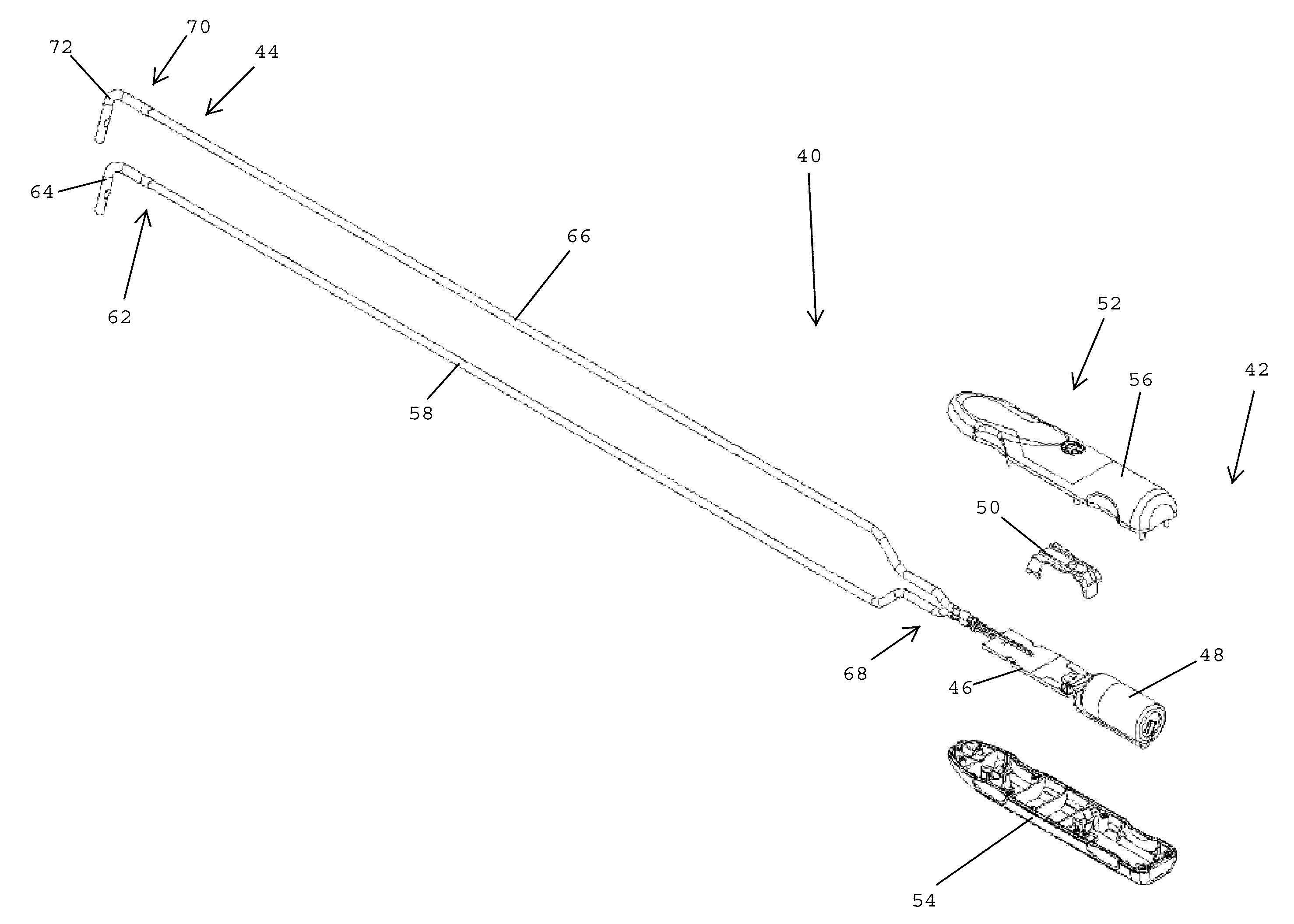
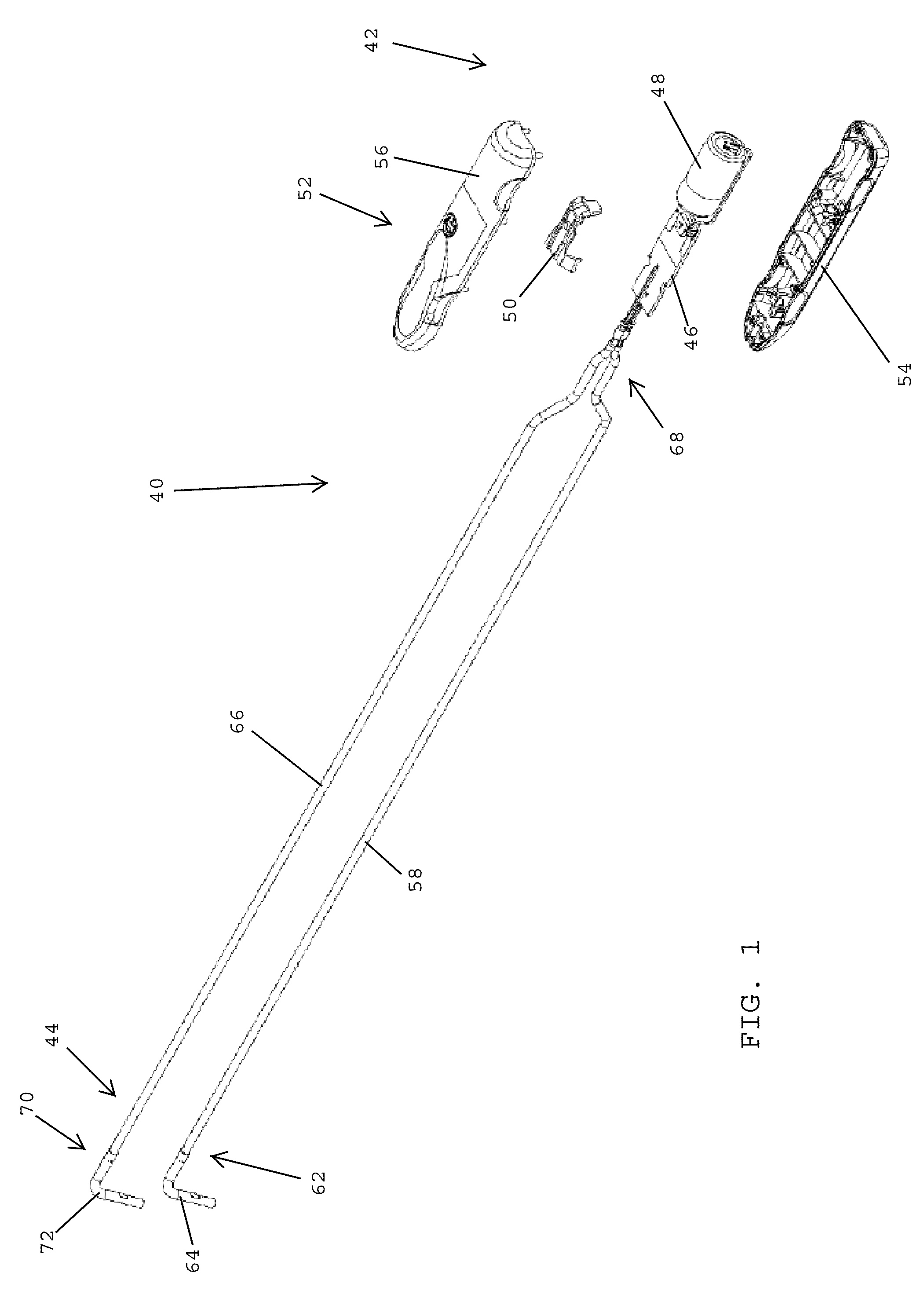
[0048]Referring to FIG. 1, in one preferred embodiment of the present invention, a surgical illumination device 40 for surgical tools and surgical sites preferably has a proximal end 42 and a distal end 44. In one embodiment, the surgical illumination device preferably includes a circuit board 46, a power source 48, such as a lithium cell battery, and a circuit interrupt 50 that prevents the surgical illumination device from operating until the circuit interrupt has been removed. The surgical illumination device 40 preferably includes a housing 52 that encases the circuit board 46 and the power source 48. In one embodiment, the housing 52 desirably includes a lower housing part 54 and an upper housing part 56 that covers the lower housing part.

[0049]In one embodiment, the printed circuit board 46 preferably includes electronic components for controlling operation of the surgical illumination device 40. In one embodiment, the electronic components may include one or more microprocess...


PUM


Abstract

A surgical illumination device includes a LED with a positive terminal, a negative terminal, and a heat transfer pad. A flexible circuit has first and second electrically conductive traces extending from a proximal end to a distal end thereof. The first conductive trace is electrically interconnected with the positive terminal, the second conductive trace is electrically interconnected with the negative terminal, and a heat transfer window on the flexible circuit is aligned with the heat transfer pad. The illumination device includes a heat sink having a distal end with a distal end face. A thermally conductive adhesive pad is disposed between the LED and the distal end face of the heat sink. The thermally conductive adhesive pad is aligned with the heat transfer window of the flexible circuit and the heat transfer pad of the LED base.

Description

BACKGROUND OF THE INVENTION[0001]1. Field of the Invention[0002]The present invention is generally related to illumination and is more specifically related to surgical illumination devices used during medical examinations and surgical procedures.[0003]2. Description of the Related Art[0004]Ambient illumination is often inadequate for conducting safe and efficacious medical examinations and surgical procedures. Regardless of the intensity of the ambient lighting, shadows cast by medical personnel and / or other objects in a room (e.g., draperies) may prevent proper illumination of an examination site or surgical site. Moreover, when a surgical procedure is conducted inside a body cavity, providing sufficient lighting is even more difficult to achieve.[0005]Illumination devices inserted into body cavities must be safe, reliable, capable of being sterilized, capable of operating with other surgical instruments, and be easy for a physician to manipulate. Critical specification features fo...

Claims


Application Information

Patent Timeline
IPC IPC(8): A61B1/06A61B1/00A61B1/12
CPCA61B1/0684A61B1/128A61B1/0676A61B1/00096A61B1/00078A61B1/00114A61B90/30A61B90/35A61B2090/309F21V23/001F21V29/70
Inventor COPPERSMITH, DANIELLINDER, MAXIMILLIANEL KAZZAZ, MICHAEL H.
Owner ENGINEERED MEDICAL SOLUTIONS
Learn More