Float loop textile electrodes and methods of knitting thereof

Active Publication Date: 2015-10-22
AUTONETWORKS TECH LTD
View PDF3 Cites 17 Cited by
  • Summary
  • Abstract
  • Description
  • Claims
  • Application Information

AI Technical Summary

Benefits of technology

[0018]To be able to conduct continuous long term monitoring, a textile substrate is used to develop dry textile electrodes for sensing physiological parameters of a living being such as ECG signals. The dry textile electrodes include multiple float loops formed on the skin-side surface of the electrodes, facilitating acquisition of heart ECG signals having clinical quality. The float

Problems solved by technology

The off-line analysis may often prove to be too-late, and the health diagnosis is usually not accurate enough to trigger a definite intervention or instruction to the user.
However, all the other parts of the garment may be not as tight.
However, skin preparation and the use of conductive gels are always required when using conventional wet electrodes, which is not user friendly and, typically, is therefore in clinical use only.
In terms of the convenience of the ECG signal measurement process, these procedures usually create trouble for users, especially in daily life applications for long-term monitoring.
In particular, the use of conductive gels inevitably leaves residues on the chest.
The gel may also leak out of the wet ECG electrodes, causing a short circuit betwee

Method used

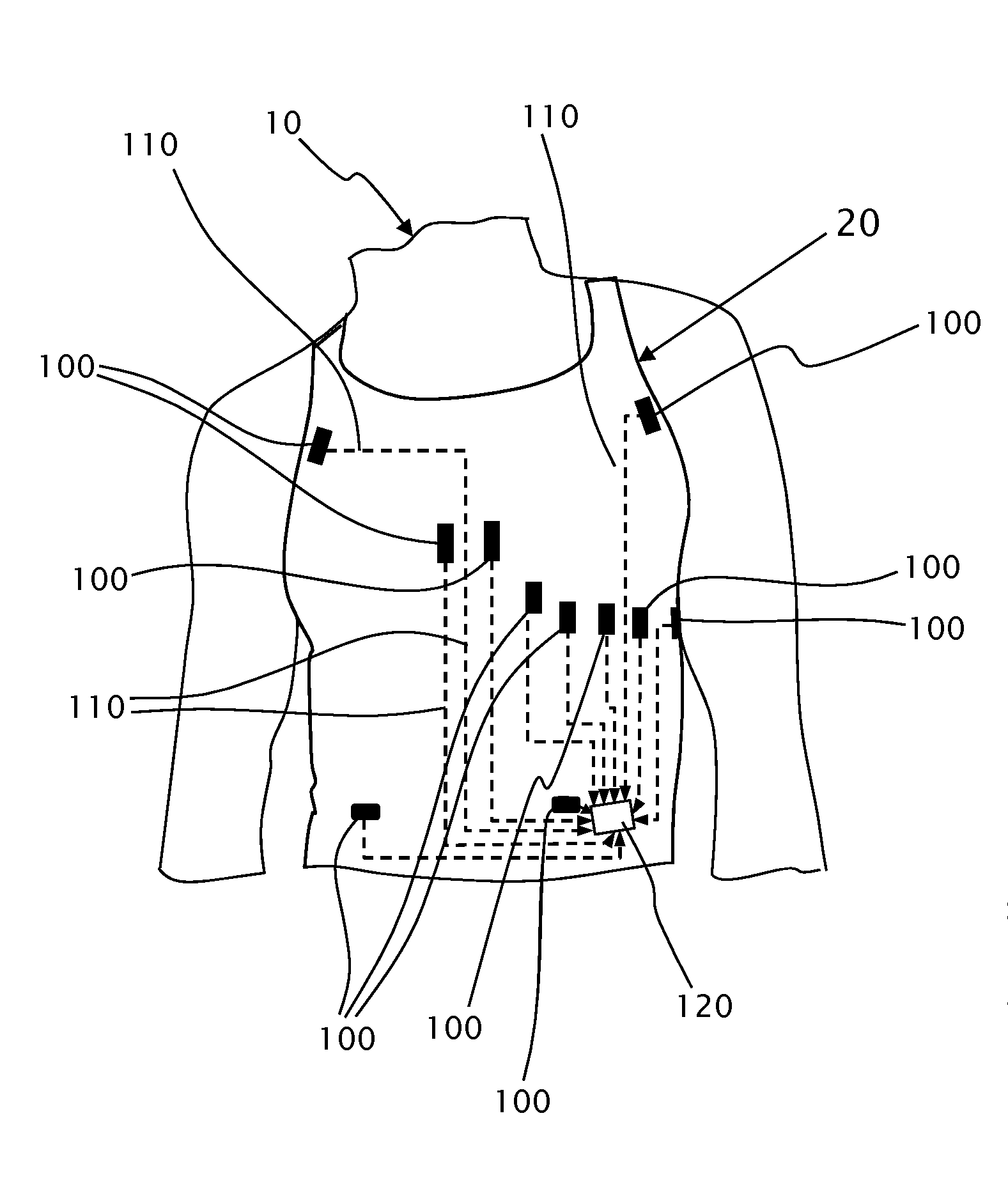
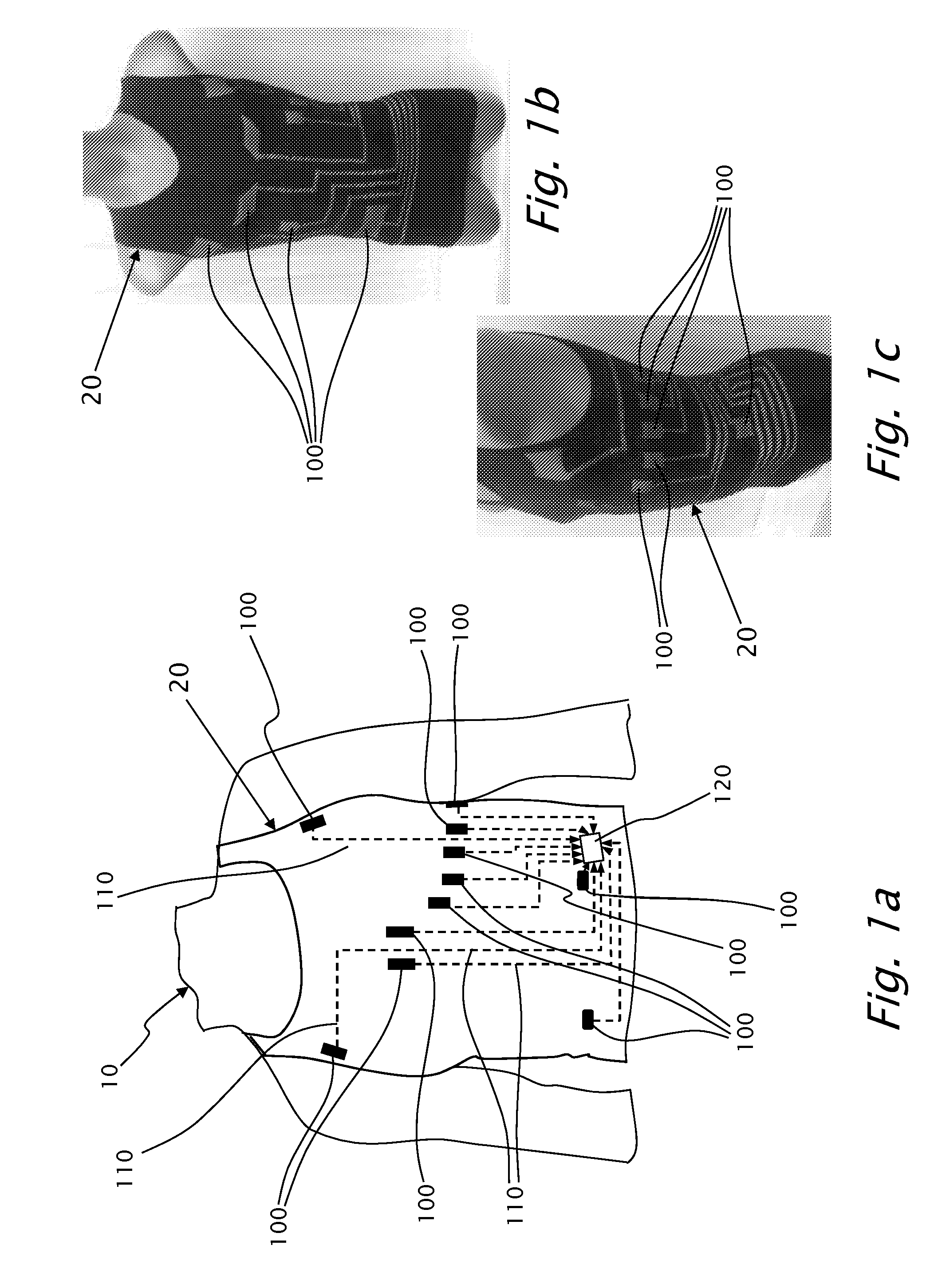
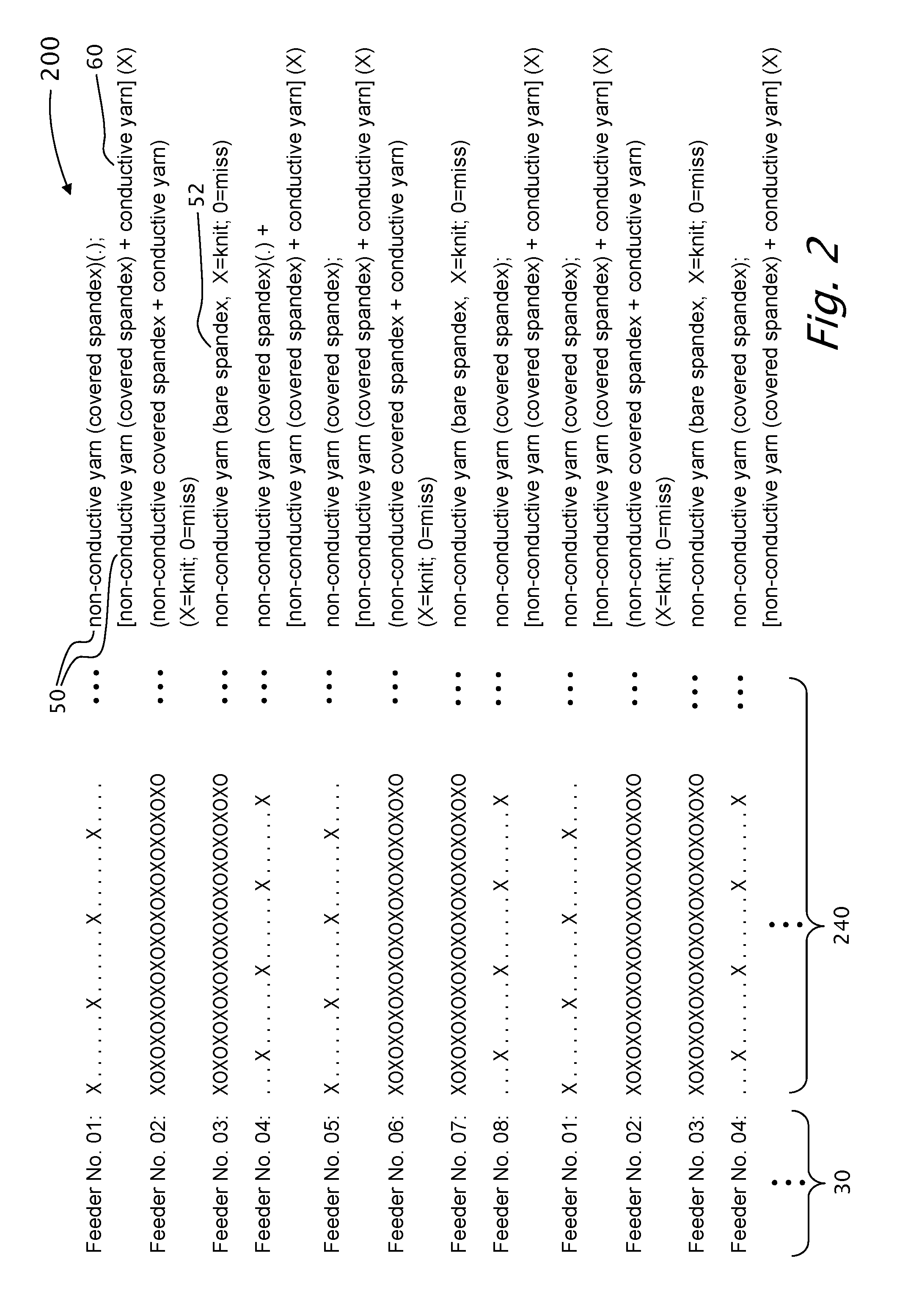

Image

  • Float loop textile electrodes and methods of knitting thereof
  • Float loop textile electrodes and methods of knitting thereof
  • Float loop textile electrodes and methods of knitting thereof

Examples


Embodiment Construction

[0047]The present invention will now be described more fully hereinafter with reference to the accompanying drawings, in which preferred embodiments of the invention are shown. This invention may, however, be embodied in many different forms and should not be construed as limited to the embodiments set forth herein; rather, these embodiments are provided, so that this disclosure will be thorough and complete, and will fully convey the scope of the invention to those skilled in the art.

[0048]An embodiment is an example or implementation of the inventions. The various appearances of “one embodiment,”“an embodiment” or “some embodiments” do not necessarily all refer to the same embodiments. Although various features of the invention may be described in the context of a single embodiment, the features may also be provided separately or in any suitable combination. Conversely, although the invention may be described herein in the context of separate embodiments for clarity, the invention...


PUM

PropertyMeasurementUnit
Electrical conductivityaaaaaaaaaa
Densityaaaaaaaaaa
Electrical conductoraaaaaaaaaa

Abstract

A method for knitting a garment having a tubular form, including knitting at least one conductive textile electrode on a machine having N participating feeders and M needles. The method includes the steps of continuously knitting the tubular form with one or more flexible non-conductive yarns, and knitting the electrode integrally within the tubular form, using a conductive yarn, in addition to the non-conductive yarns. The conductive yarn is knitted in a float-loop form by knitting a stitch and skipping over y needles, as follows: repeatably knitting a line segment Lk, using feeder Fi and starting at needle D1; and knitting line segment Lk+1, using the next feeder and start stitching the first float-loop at needle D1+s where 0<s<y. The tubular form has a preconfigured 10 knitting density, wherein the electrode has a knitting density that is higher than the preconfigured knitting density of the tubular form.

Description

CROSS REFERENCE TO RELATED APPLICATIONS[0001]This application claims the benefit under 35 USC 119(e) from U.S. provisional application 61 / 729,548 filed Nov. 24, 2012, and from U.S. provisional application 61 / 763,961 filed Feb. 13, 2013, the disclosures of which are included herein by reference.FIELD OF THE INVENTION[0002]The present invention relates to real-time health monitoring systems and more particularly, the present invention relates to knitted electrodes embedded into a knitted garment at preconfigured locations, wherein the electrodes and the garment form one piece. The electrodes are interconnected with a processor to form a health monitoring system.[0003]The present invention provides novel dry textile contact electrodes, for measuring physiological parameters of a living being such as ECG signals and / or other vital signals such (EEG), electroencephalogram (EOG), electrooculogram and other medical measurements, wherein disposed adjacently to the skin of the monitored livi...

Claims


Application Information

Patent Timeline
IPC IPC(8): A61B5/00D04B1/24D04B1/14A61B5/0408
CPCA61B5/6804A61B5/04085D04B1/246D04B1/14D10B2509/00A61B2562/125D10B2101/20D10B2401/18A61B2562/0209A61B5/6805A41D13/1281D10B2403/02431G06F1/163D04B1/12D04B1/18A61B2562/0215A61B5/25A61B5/282D04B1/102D04B1/16
Inventor SHOSHANI, BOAZBEN DAVID, RENEN
Owner AUTONETWORKS TECH LTD
Why Eureka
Try Eureka