Rack shaft and method for manufacturing rack shaft

Inactive Publication Date: 2015-10-22
JTEKT CORP
View PDF5 Cites 11 Cited by
  • Summary
  • Abstract
  • Description
  • Claims
  • Application Information

AI Technical Summary

Benefits of technology

[0009]An object of the present invention is to provide a rack shaft in a dual-pinion electric power steering apparatus, which en

Problems solved by technology

Furthermore, in the dual-pinion electric power steering apparatus, when the rack shaft in JP 2006-103644 A, which is hollow as a whole, is used, a desired meshing streng

Method used


Image

  • Rack shaft and method for manufacturing rack shaft
  • Rack shaft and method for manufacturing rack shaft
  • Rack shaft and method for manufacturing rack shaft

Examples


Example

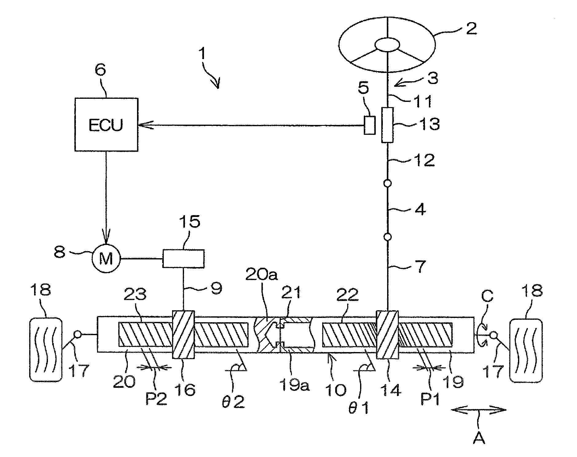
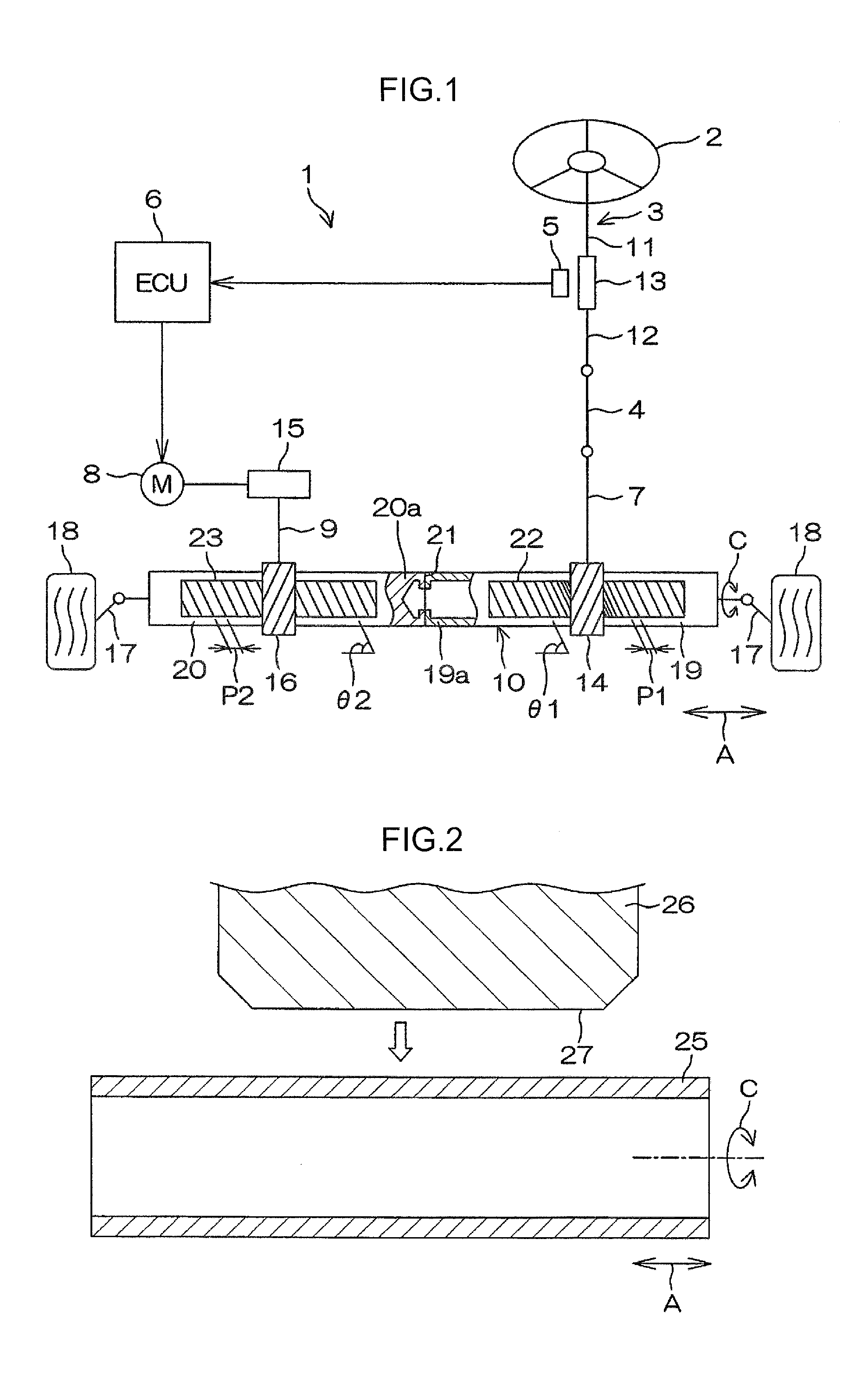
[0020]An embodiment of the present invention will be described below in detail with reference to the attached drawings. FIG. 1 is a schematic diagram depicting a general configuration of an electric power steering apparatus 1 of the present embodiment of the present invention. As seen in FIG. 1, the electric power steering apparatus 1 mainly includes a steering shaft 3 to which a steering wheel 2 is coupled, an intermediate shaft 4, a torque sensor 5, an electronic control unit (ECU) 6, a first pinion shaft 7, an electric motor 8, a second pinion shaft 9, and a rack shaft 10. The first pinion shaft 7 transmits manual steering force from the steering wheel 2 to the rack shaft 10. The second pinion shaft 9 transmits steering assist force from the electric motor 8 for steering assistance to the rack shaft 10. The electric power steering apparatus 1 is what is called a dual-pinion electric power steering apparatus.

[0021]The steering wheel 2 and the first pinion shaft 7 are mechanically ...


PUM


Abstract

A rack shaft used for a dual-pinion electric power steering apparatus includes: a hollow first shaft in which a first rack for transmission of manual steering force is formed; and a solid second shaft in which a second rack for transmission of steering assist force is formed and which is coupled to the first shaft. A method for manufacturing a rack shaft includes: forming a first rack in a hollow first shaft by plastic working; coupling a solid second shaft to the first shaft after the plastic working; and forming a second rack in the second shaft by cutting after the coupling.

Description

INCORPORATION BY REFERENCE[0001]The disclosure of Japanese Patent Application No. 2014-086711 filed on Apr. 18, 2014 including the specification, drawings and abstract is incorporated herein by reference in its entirety.BACKGROUND OF THE INVENTION[0002]1. Field of the Invention[0003]The invention relates to a rack shaft and a method for manufacturing the rack shaft.[0004]2. Description of Related Art[0005]As an electric power steering apparatus, what is called a single-pinion electric power steering apparatus is known in which steering force from a steering wheel and the steering assist force of an electric motor are transmitted to a rack shaft in a steering mechanism via the same pinion. A single-pinion electric power steering apparatus is proposed in Japanese Patent Application Publication No. 2012-240563 (JP 2012-240563 A). In JP 2012-240563 A, a portion of the rack shaft in which a rack meshing with a pinion is formed is a solid shaft, and a portion of the rack shaft with no rac...

Claims


Application Information

Patent Timeline
IPC IPC(8): B62D3/12B62D65/00B21K1/76F16H55/26
CPCB62D3/126B21K1/767B62D65/00F16H55/26B21K1/768
Inventor SUZUKI, MASATERU
Owner JTEKT CORP
Why Eureka
Try Eureka