Initial crack formation device, and formation method
a formation device and crack technology, applied in the field of initial crack formation devices, can solve the problems of affecting the inability to propagate a cleaving part, and the inability to cut glass sheets g, so as to prevent the quality of glass sheets from being degraded, the risk of scattered glass particles adhering to glass sheets can be reduced.
- Summary
- Abstract
- Description
- Claims
- Application Information
AI Technical Summary
Benefits of technology
Problems solved by technology
Method used
Image
Examples
first embodiment
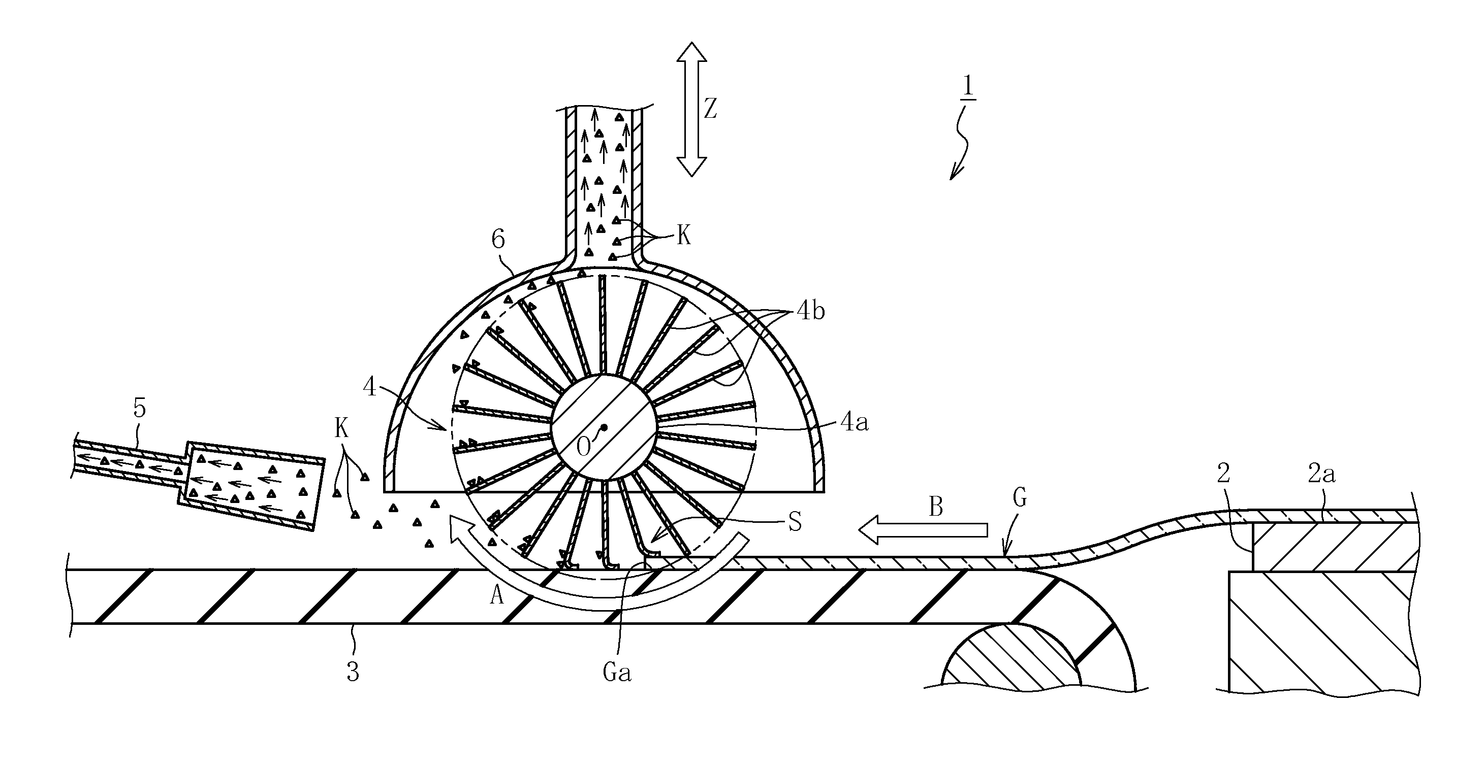
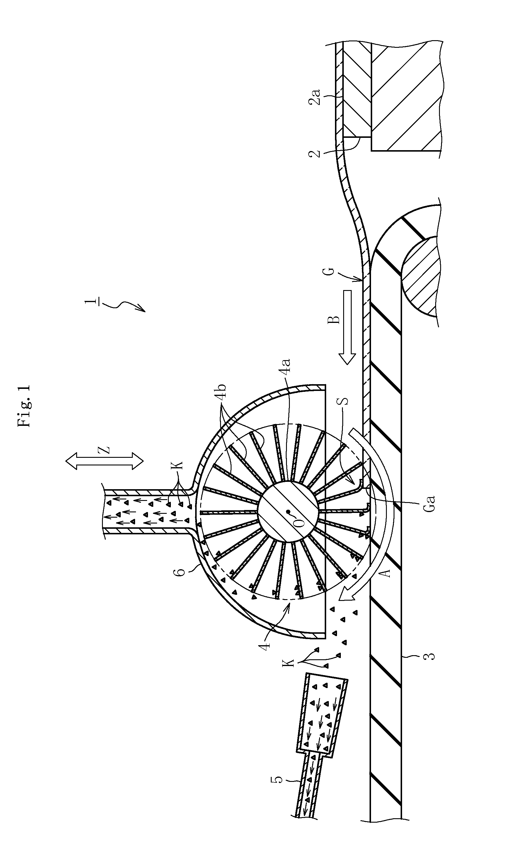
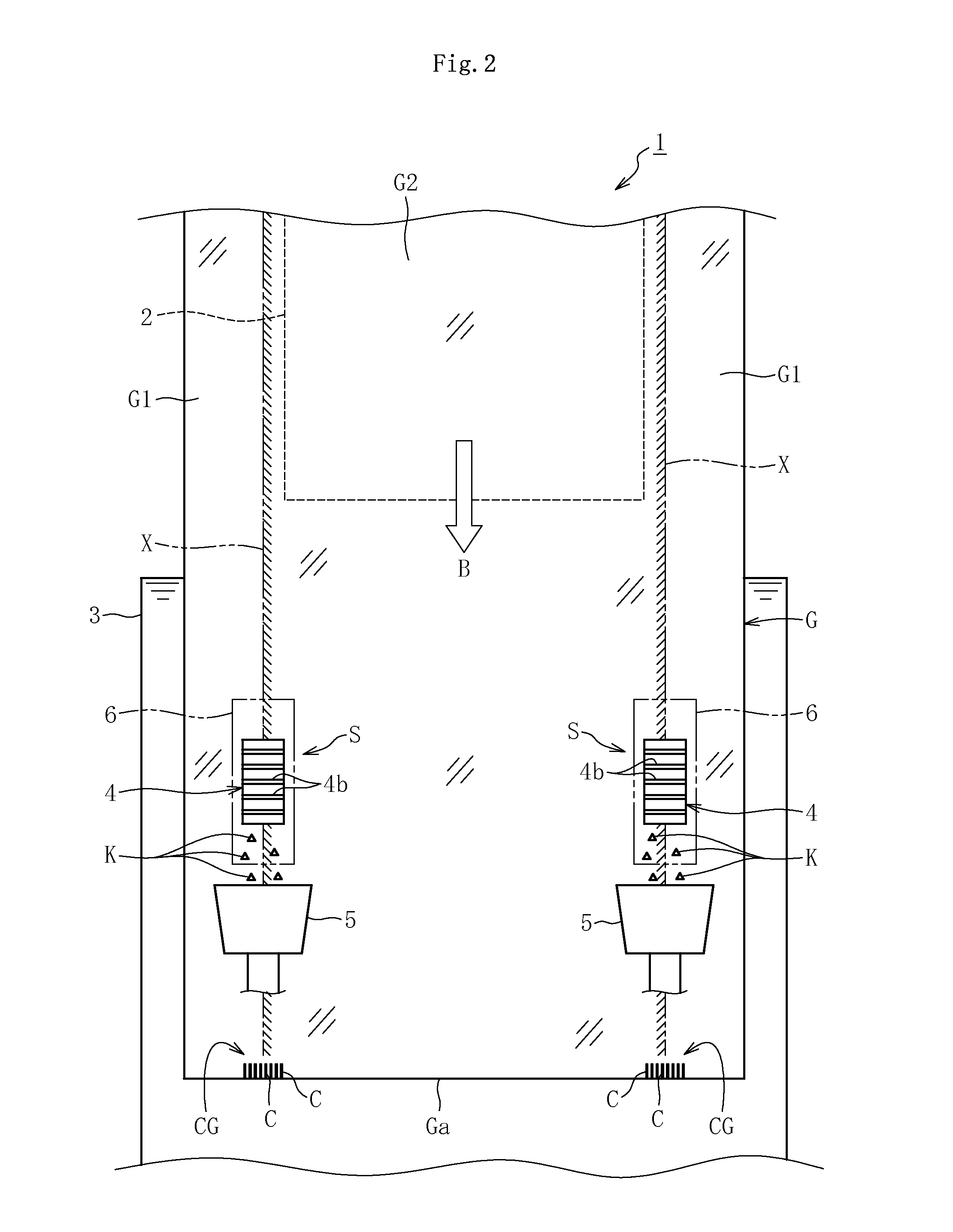
[0057]FIG. 1 is a sectional view illustrating an initial crack formation device according to the present invention. FIG. 2 is a plan view thereof. As illustrated in those figures, an initial crack formation device 1 comprises a crease removing table 2 serving as crease removing means for removing a crease formed on a glass ribbon G while allowing the glass ribbon G to pass along an upper surface 2a of the crease removing table 2, a belt conveyor 3 for conveying the glass ribbon G having passed along the crease removing table 2 in a conveyance direction B, a flap wheel 4 serving as a rotary scoring section (rotary scoring tool) for scoring, while rotating, a front-side end Ga in the conveyance direction B of the glass ribbon G during conveyance in an initial crack formation region S, and a suction device 5 and a suction device 6 serving as first suction means and second suction means for sucking glass particle K generated from the glass ribbon G during formation of an initial crack g...
second embodiment
[0079]Now, the actions and effects of an initial crack formation method using the initial crack formation device 1 according to the above-mentioned second embodiment are described.
[0080]According to the initial crack formation method using the initial crack formation device 1, in addition to the actions and effects described in the above-mentioned first embodiment, the following actions and effects are obtained. That is, in the initial crack formation method according to the first embodiment, the abrasive cloth 4b may damage the belt conveyor 3 so as to generate powder dust from the belt conveyor 3. However, in the initial crack formation method according to the second embodiment, the abrasive cloth 4b is brought into contact with only the support roller 7 except for the glass ribbon G. Then, the support roller 7 is rotated so that the movement direction along the tangent of the outer periphery of the support roller 7 is matched with the direction along the tangent of the outer peri...
third embodiment
[0081]Now, an initial crack formation device according to the present invention is described with reference to the accompanying drawings.
[0082]FIG. 6 is a sectional view illustrating an initial crack formation device 1 according to the third embodiment of the present invention. The initial crack formation device 1 according to the third embodiment is different from the initial crack formation device according to the above-mentioned first embodiment in that: both the suction devices 5 and 6 are removed; the rotational peripheral speed of the flap wheel 4 is different; and the area in which the initial crack group CG is formed in the end Ga of the glass ribbon G is different. Note that, in this embodiment, the flap wheel 4 forms an initial crack formation section (initial crack formation tool).
[0083]The flap wheel 4 is rotated so that the rotational peripheral speed thereof becomes substantially equal to the conveyance speed of the glass ribbon G during formation of the initial crack ...
PUM
| Property | Measurement | Unit |
|---|---|---|
| thickness | aaaaa | aaaaa |
| thickness | aaaaa | aaaaa |
| thickness | aaaaa | aaaaa |
Abstract
Description
Claims
Application Information
 - R&D
- Intellectual Property
- Life Sciences
- Materials
- Tech Scout
- Unparalleled Data Quality
- Higher Quality Content
- 60% Fewer Hallucinations
Browse by: Latest US Patents, China's latest patents, Technical Efficacy Thesaurus, Application Domain, Technology Topic, Popular Technical Reports.
© 2025 PatSnap. All rights reserved.Legal|Privacy policy|Modern Slavery Act Transparency Statement|Sitemap|About US| Contact US: help@patsnap.com


