Cladding assembly

Active Publication Date: 2015-10-22
LEE DUANE
View PDF26 Cites 25 Cited by
  • Summary
  • Abstract
  • Description
  • Claims
  • Application Information

AI Technical Summary

Benefits of technology

[0008]It is an object of the present invention to provide an improved or alternate cladding system. In particular, a cladding assembly that

Problems solved by technology

A problem associated with typical modern cladding systems is that they are labour intensive and time consuming to assemble and install.
The act of installing a typical cladding unit is particularly labour intensive and time consuming, often initially requiring the fitting of various frames and brackets to the structure or building prior to fitting the actual cladding.
As such, a further and resultant problem associated with typical modern

Method used


Image

  • Cladding assembly
  • Cladding assembly
  • Cladding assembly

Examples


Embodiment Construction

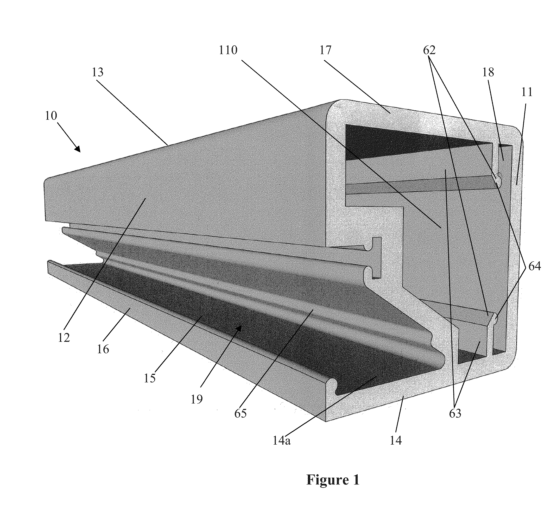
[0160]FIG. 1, in particular, shows a frame member (10) adapted to be joined together with other frame members to form a frame of a preformed panel. The frame member (10) includes at least four walls including an inner frame wall (11), an opposed outer frame wall (12), a panel abutting wall (13) and an opposed structure abutting wall (14) with a free end (15) having an outer edge protrusion (16). The frame member (10) includes at least two ends (17), each end (17) defining a slot (18) and channel (110) each of which is capable of at least partially receiving a joining component for joining the frame member (10) with another frame member to form the frame. A receiving opening (19) is defined between a portion of the outer frame wall (12) and the outer edge protrusion (16) for receiving one or more tags (i.e., fasteners) which engage the outer edge protrusion (16) for, in use, fastening the frame member (10) and thereby the preformed panel to a structure.

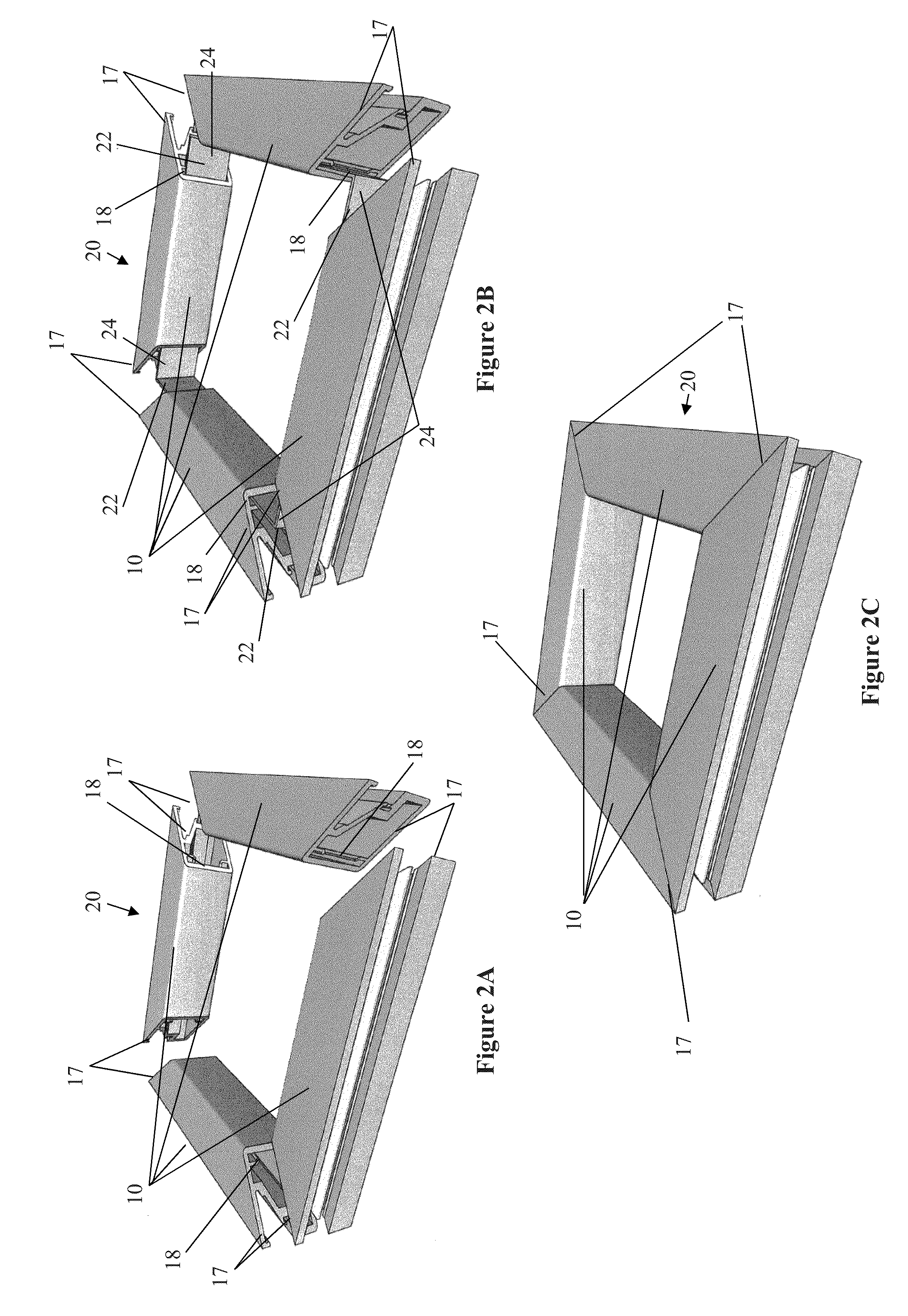
[0161]FIGS. 2A to 2C and 3A to ...


PUM


Abstract

The present invention concerns a frame member (10), a frame formed from the frame member (10) and a panel including the frame for use in a cladding assembly for cladding a structure. The frame member (10) of the present invention is adapted to be joined together with other frame members (10) to form the frame, each frame member (10) includes at least four walls including an inner frame wall (11), an opposed outer frame wall (12), a panel abutting wall (13) and an opposed structure abutting wall (14) having a free end (15) with an outer edge protrusion (16). A receiving opening (19) is defined between a portion of the outer frame wall (12) and the outer edge protrusion (16) for receiving one or more fasteners which engage the outer edge protrusion (16) for, in use, fastening the frame member (10) and thereby the frame and preformed panel to the structure.

Description

TECHNICAL FIELD[0001]The present invention relates to a cladding assembly for attachment to an external surface of a structure or building. In particular, the present invention relates to a preformed panel for use in a cladding assembly.BACKGROUND ART[0002]The facade or external appearance of a structure or building is often one of the most important visual aspects of the structure or building from a design standpoint.[0003]The advent of modern building practices through the use of structural steel and reinforced concrete has dramatically changed the way facades are used. The importance of load-bearing walls has diminished, which, in turn, has resulted in a decreased use of traditional masonry facades and an increased use of modern cladding systems that are suspended from or attached to a structure or building to form a facade.[0004]A problem associated with typical modern cladding systems is that they are labour intensive and time consuming to assemble and install. This is because,...

Claims


Application Information

Patent Timeline
IPC IPC(8): E04F13/08
CPCE04F13/0801E04F13/0736E04F13/0807E04F13/0862E04F13/0825E04F13/0826E04F13/12
Inventor DAY, SIMONLEE, RICHARD ANTHONY
Owner LEE DUANE
Why Eureka
Try Eureka