
System and method for stereophotogrammetry

a stereophotogrammetry and system technology, applied in the field of stereophotogrammetry system and method, can solve the problems of poor or inconsistent 3d image, limited commercial camera availability, and activation lag difference between, so as to reduce activation lag difference and increase the frame rate of capture

Inactive Publication Date: 2015-10-22
ZHANG XIUCHUAN +1
View PDF4 Cites 15 Cited by
  • Summary
  • Abstract
  • Description
  • Claims
  • Application Information

AI Technical Summary

Benefits of technology

The present invention provides a system and method for stereophotogrammetry by synchronizing and coordinating the activation of groups of cameras sequentially to reduce the activation lag difference (ALD) between them and create a consistent 3D image. This results in a synchronized set of images for the generation of a 3D model and a smoother 4D image of the object of capture. Additionally, by utilizing multiple groups of cameras or stereophotogrammetric units to activate in sequence, the frames rate of capture of a moving object is increased. The controller may additionally be configured to effect the sequential and alternating triggering of a plurality of stereophotogrammetric units.

Problems solved by technology

Current stereogrammetry systems comprising commercial DSLR cameras are generally only capable of capturing a 3D model at less than 5 frames per second.
A main contributor to this limitation is the activation lag difference (ALD) between the cameras.
The ALD may result in image desynchronization during capture, making it difficult for any 3D modeling and / or recording software to compare the different images to locate key pixels, thus resulting in a poor or inconsistent 3D image.
Another contributor is the technical limitation of available commercial cameras, which may only be able to shoot at are predetermined number of frames per second.
As a result, the resulting 4D image generated may also be low or choppy due to the sparse number of frames captured per second.

Method used


Image

  • System and method for stereophotogrammetry
  • System and method for stereophotogrammetry
  • System and method for stereophotogrammetry

Examples


Embodiment Construction

[0027]As illustrated by the accompanying drawings, the present invention is directed to a stereophotogrammetric system and method for capturing three-dimensional objects.

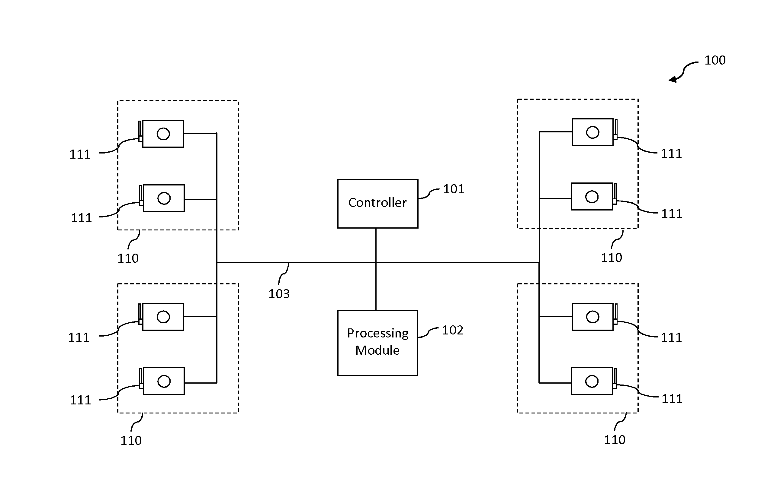
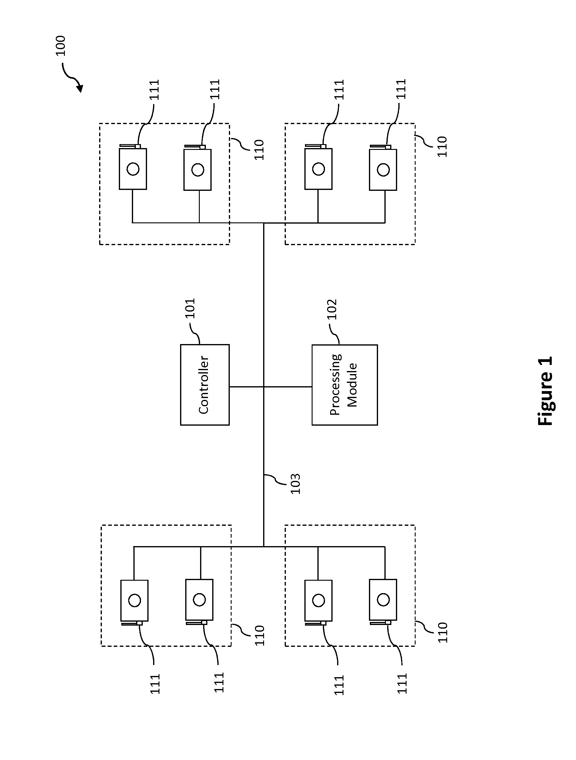
[0028]Accordingly, as illustrated in FIG. 1, a system 100 may comprise at least one stereophotogrammetric unit 110 communicably connected to a controller 101. A processing module 102 may further be connected to the controller 101 and / or to the at least one stereophotogrammetric unit 110.

[0029]Each stereophotogrammetric unit 110 comprises a plurality of cameras 111 structured and disposed in spaced-apart relation, such as to capture a set of images of an object at appropriate different angles. The illustrations show two cameras 111 for illustrative purposes, but it should be understood that in various embodiments, three or more cameras may be used at different angles to capture a larger set of images of an object at different angles. For example, full body scan may require around a hundred cameras, whereas a simple o...


PUM


Abstract

The invention is directed to a stereophotogrammetric system and method for generating 3D images. A stereophotogrammetric unit, having a plurality of cameras, is structured to capture a set of images of an object at different angles. A controller is communicably connected to the stereophotogrammetric unit, and is configured to facilitate the simultaneous triggering of the plurality of cameras through a synchronized trigger signal, such that the cameras will capture respective images of the object at the same time. A processing module is configured to generate 3D image from the set of images captured. The controller may further be configured to facilitate the sequential triggering of a plurality of stereophotogrammetric units, such that the object in motion may be captured at increased frames per second. The processing module may further be configured to link together the plurality of 3D images in sequence to then create a 4D image.

Description

BACKGROUND OF THE INVENTION[0001]1. Field of the Invention[0002]The present invention generally relates to a system and method for stereophotogrammetry, wherein objects are captured and 3D and 4D images of the objects are then generated. Specifically, a stereophotogrammetric unit comprising a plurality of cameras is calibrated to activate with various delays, such that the 2D image captures of an object at different angles are synchronized across the plurality of cameras, thus resulting in a consistent and higher quality 3D image. Further, a plurality of stereophotogrammetric units may be triggered in sequence at predetermined time intervals to increase the frame rate of capture, which results in a higher quality 4D image.[0003]2. Description of the Related Art[0004]Stereophotogrammetry generally refers to the calculation of height or depth dimensions of an object by contrasting at least two overlapping images taken from different angles. By using the geometry based on the intersect...

Claims


Application Information

Patent Timeline
IPC IPC(8): H04N13/02H04N13/296
CPCH04N13/02G01C11/06H04N13/243H04N13/246H04N13/296H04N13/20
Inventor ZHANG, XIUCHUANZHANG, JINGYI
Owner ZHANG XIUCHUAN
Learn More