Damping device

a technology of adamant device and a shaft, which is applied in the direction of vibration dampers, racket sports, sports apparatus, etc., can solve the problems of unsatisfactory the frequency of vibrations that result from an off-center strike is generally unpleasant to the golfer, and the device has not been found to provide satisfactory effects. , to achieve the effect of improving the damping effect of the devi

Active Publication Date: 2015-10-29
PRO CORE TECH
View PDF17 Cites 7 Cited by
  • Summary
  • Abstract
  • Description
  • Claims
  • Application Information

AI Technical Summary

Benefits of technology

[0009]Accordingly, one aspect of the invention provides a damping device, e.g. for a golf club, the device comprising an anchor element and a damping element or frequency filter interconnected by a rigid rod, wherein the anchor element is configured to anchor, in use, the device within the shaft of a striking device such as a golf club, e.g. within a lower and / or constant diameter section of the shaft and / or at or adjacent the center of gravity thereof, such that the damping element or frequency filter is in contact with an internal surface of the shaft to dampen vibrations, e.g. longitudinal and / or twisting vibrations, therein or thereof.
[0010]It will be appreciated by those skilled in the art that the provision of an anchor and damping element or frequency filter interconnected by a rigid rod improves the damping effect of the device. It will also be understood by those skilled in the art that the shaft of a golf club tapers for most of the length thereof except at the bottom of the shaft, e.g. adjacent the head of the club.
[0014]The anchor element or sleeve or collar or collet may be fixed or secured to the rod, for example by a threaded engagement or adhesive or even molded over the rod. In some embodiments, the sleeve or collar or collet extends beyond the end of the rod, for example to reduce the cantilever effect and / or to alter the rigidity with which the anchor secures and / or cantilevers the rod and / or to provide a further damping effect.
[0018]The damping element or frequency filter or sleeve may comprise a base sleeve and / or a resilient material or layer, for example a foam material or layer, e.g. over-wrapped around the base sleeve. In some embodiments, the damping element or frequency filter comprises a base sleeve with a spiral wrapped resilient material or strip. In some embodiments, the damping element or frequency filter comprises a resilient material or layer, for example a foam material or layer, that is mounted or secured or wrapped directly on or to or around the rod and / or covered by an outer layer or casing, for example encased in shrink wrap, e.g. to prevent damage or catching of the resilient material or layer when the device is installed or removed. The resilient material or layer may also be molded onto or over the rod and / or may comprise formations or features, for example surface formations or features, e.g. to improve the damping effect. The resilient material is preferably selected to optimise the damping device's effectiveness.
[0021]The anchoring element may comprise a shore hardness, e.g. measured at the resilient material within the collet, of between 35 and 50, preferably 40 to 45. The damping element or frequency filter may compose a shore hardness of between 40 and 55, preferably 45 to 50. It has been observed that this configuration provides surprisingly effective damping.
[0026]A further aspect of the invention provides a golf club comprising a shaft, a head and a damping device as described above received or disposed within the shaft. Preferably, the anchor element of the damping device is located and / or anchored within a section, e.g. a lower of the shaft that has a substantially constant diameter and / or at or adjacent the center of gravity of the golf club, e.g. such that the damping element or frequency filter is in contact with an internal surface of the shaft to dampen vibrations therein.

Problems solved by technology

It is known that the impact of a golf club hitting a golf ball causes vibrations through the shaft of the club.
The frequency of the vibrations that result from an off-center strike is generally unpleasant to the golfer and several attempts have been made to control and / or mitigate such frequencies through the use of damping devices.
However, none of these devices have been found to provide satisfactory results.

Method used


Image

  • Damping device
  • Damping device
  • Damping device

Examples


Embodiment Construction

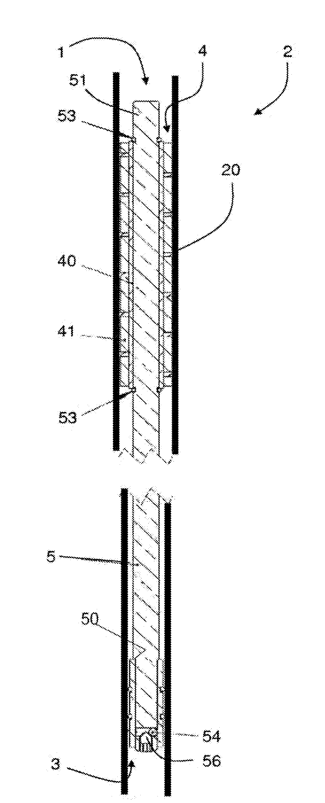
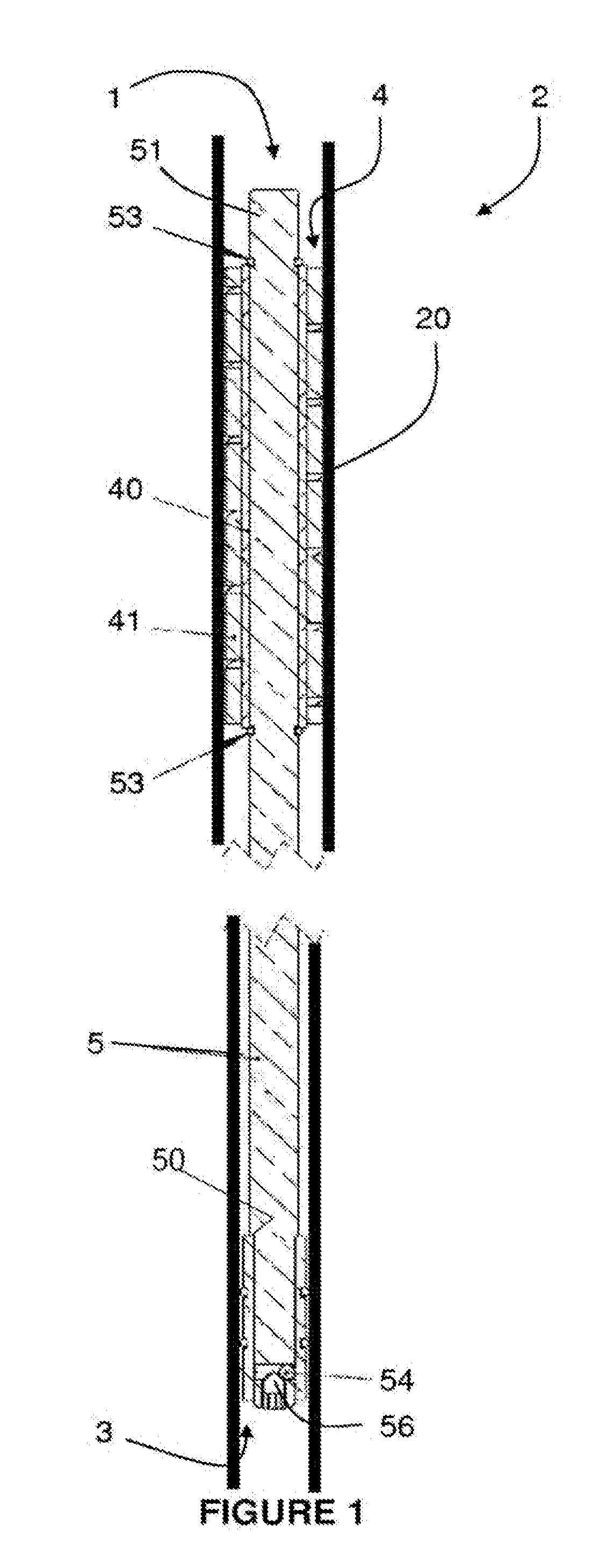
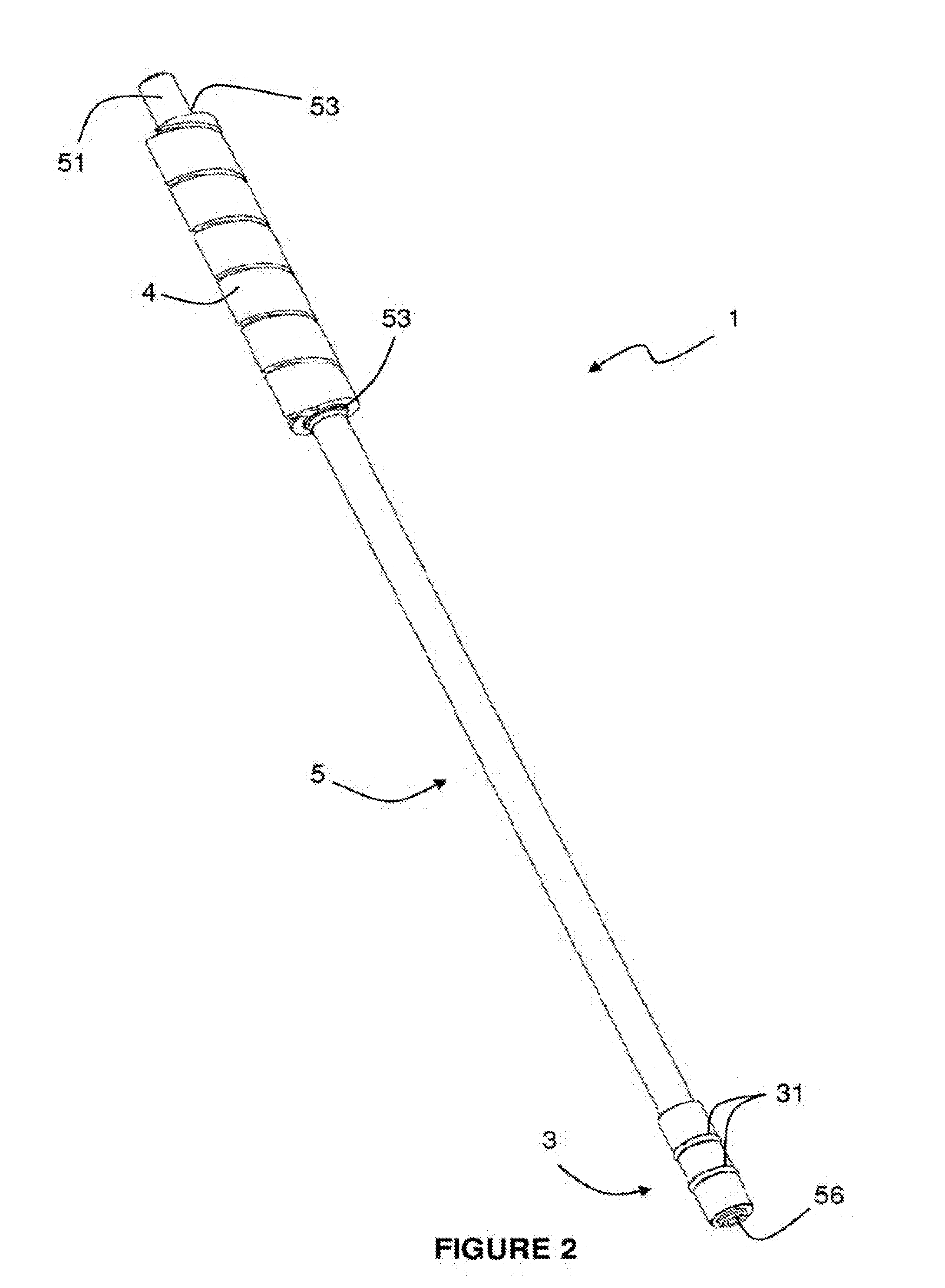
[0044]Referring now to FIGS. 1 to 4, there is shown a damping device 1 for incorporation into a golf club 2, which is a putter in this embodiment. The damping device 1 is an insert that includes an anchor element 3 and a damping element or frequency filter 4 that are interconnected by a rigid aluminum rod 5. The anchor element 3 is in the form of a brass sleeve in this embodiment that is removably mounted to a first end of the rod 5 and that has a larger diameter than the rod 5. The anchor sleeve 3 includes a pair of spaced grooves 30 with an O-ring 31 received in each groove 30. The use of brass provides a relatively heavy component adjacent the head (not shown) of the putter 2. The device 1 is therefore configured to maintain the position of the center of gravity of the putter 2 despite the addition of the damping device 1. In this embodiment, the device 1 is configured such that the overall weight, or dead weight, of the putter 2 is increased by approximately 100 grams, but the c...


PUM

PropertyMeasurementUnit
shore hardnessaaaaaaaaaa

Abstract

A golf club (2) comprising a shaft (20), a head and a damping device (1, 100). The damping device (1, 100) includes an anchor element (3, 103) and a damping element (4, 104) interconnected by a rigid rod (5, 105). The anchor element (3, 103) is anchored within the lower section of the shaft (20) that has a substantially constant diameter such that the damping element (4, 104) is in contact with an internal surface of the shaft (20) to dampen vibrations therein.

Description

CROSS-REFERENCE TO RELATED APPLICATION(S)[0001]The present application is a division of U.S. patent application Ser. No. 13 / 808,715 filed on Jan. 7, 2013 from which it derives priority and which is incorporated herein by reference. U.S. patent application Ser. No. 13 / 808,715 is in turn a National Stage Entry of PCT / GB2011 / 051304 filed on July 12, 2011.BACKGROUND OF THE INVENTION[0002]1. Field of the Invention[0003]This invention relates generally to a damping device, particularly for golf clubs. More specifically, although not exclusively, this invention relates to a damping device for a golf putter.[0004]2. Description of the Background[0005]It is known that the impact of a golf club hitting a golf ball causes vibrations through the shaft of the club. The frequency of these vibrations will generally indicate whether the ball has been struck using the correct portion of the club head, the so-called ‘sweet spot’, or whether contact has been made off the center of the sweet spot. The ...

Claims


Application Information

Patent Timeline
Patent Type & Authority Applications(United States)
IPC IPC(8): A63B53/10A63B59/00
CPCA63B59/0092A63B53/10A63B53/00A63B53/007A63B57/60A63B60/36A63B60/54Y10T29/49826A63B53/12F16F7/00
Inventor HICKS, DAVID RAYMOND
Owner PRO CORE TECH
Why Eureka
Try Eureka