Additive Manufacturing Machine

a manufacturing machine and additive technology, applied in the direction of additive manufacturing processes, manufacturing tools, manufacturing enclosures, etc., can solve the problems of contaminating the interior of the chamber, waste of powdered materials removed from the top surface of the stage, etc., and achieve the effect of preventing the waste of powdered materials

Inactive Publication Date: 2015-10-29
JEOL LTD
View PDF2 Cites 32 Cited by
  • Summary
  • Abstract
  • Description
  • Claims
  • Application Information

AI Technical Summary

Benefits of technology

[0011]In consideration of the foregoing problems, it is an object of the present invention to provide an additive manufacturing machine capable of stably supplying a powdered material onto a support stage and suppressing the interior of a processing chamber from being contaminated with the powdered material.
[0013]The additive manufacturing machine according to the present invention does not have any transport pipe that would normally be clogged up with powdered material. Therefore, a powdered material can be stably supplied onto the support stage. The powdered material for creating a 3D object is received in plural volumes within the cartridge body of the powder cartridge. This can suppress the interior of the processing chamber from being contaminated with the powdered material. It is possible to prevent waste of the powdered material.

Problems solved by technology

Furthermore, in the technique disclosed in patent document 1, the powdered material removed from the top surface of the stage is wasted.
In addition, when powdered material is transported by the restrictive member, the material scatters within the processing chamber and adheres to the inner wall of the chamber, thus contaminating the interior of the chamber.

Method used


Image

  • Additive Manufacturing Machine
  • Additive Manufacturing Machine
  • Additive Manufacturing Machine

Examples


first embodiment

1. First Embodiment

1-1. Configuration of Additive Manufacturing Machine

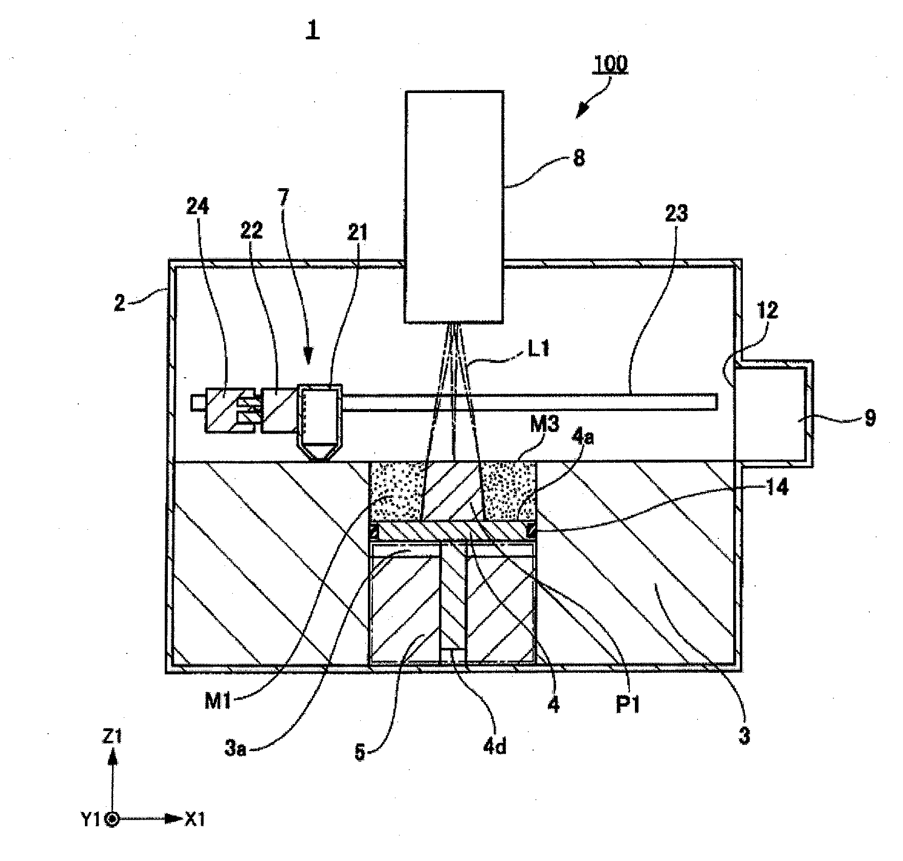
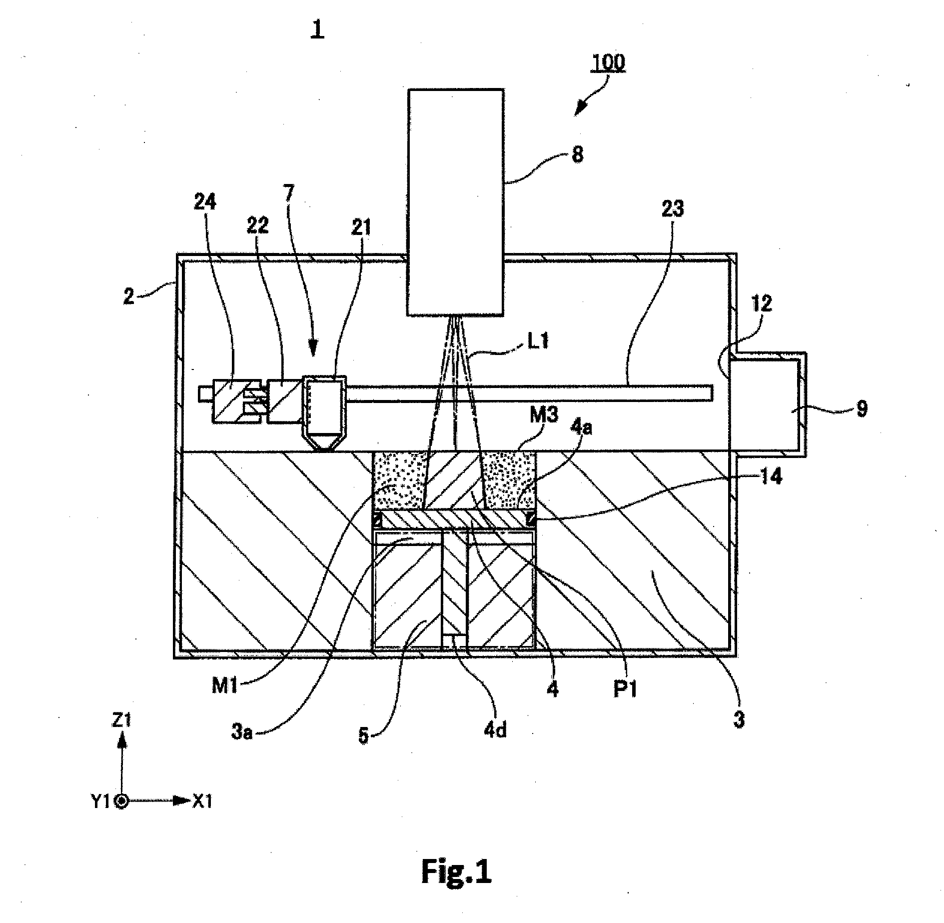
[0049]A first embodiment of the additive manufacturing machine of the present invention is first described by referring to FIG. 1, which schematically shows the machine, 1. The additive manufacturing machine 1 shown in FIG. 1 is used to create a 3D object by irradiating a powdered material consisting of a metal such as titanium, aluminum, or iron with an electron beam to melt the material and stacking layers of the powdered material solidified on top of each other.

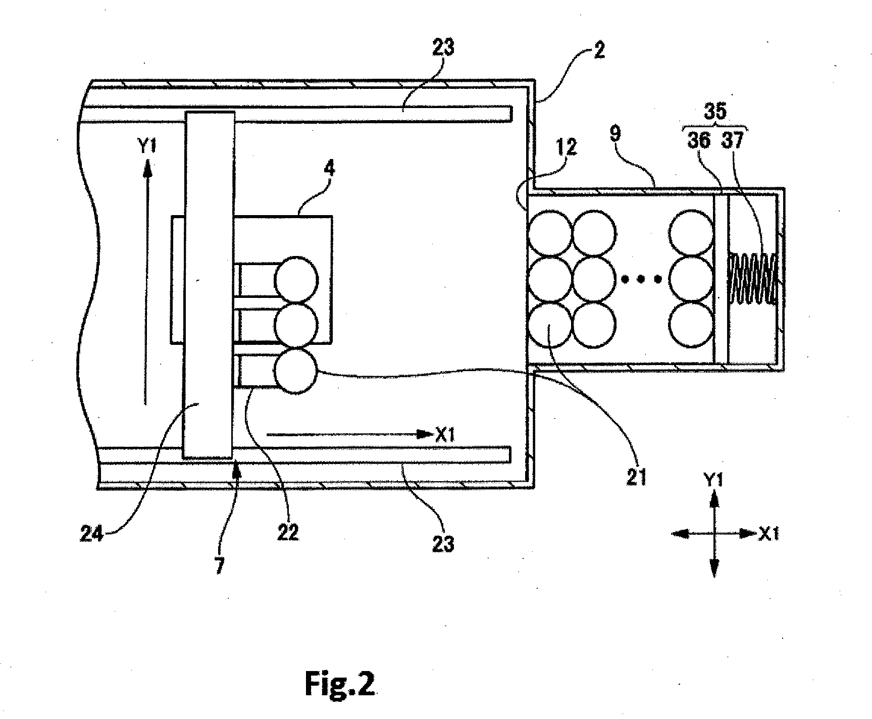
[0050]The additive manufacturing machine 1 has a hollow processing chamber 2, an additive manufacturing frame 3, a support stage 4 in the form of a flat plate, a stage driving mechanism 5, a powder supply unit 7, an electron gun 8, and a cartridge housing receptacle 9. A direction that is parallel to one surface of the stage 4 is herein referred to as the first direction X1. A direction that is perpendicular to the first direction X1 and is parallel to ...

second embodiment

2. Second Embodiment

[0080]A second embodiment of the additive manufacturing machine of the present invention is next described by referring to FIGS. 6-8. FIG. 6 is a schematic plan view of an additive manufacturing machine, 41, associated with the second embodiment. FIG. 7 is a cross-sectional view of main portions of the additive manufacturing machine 41. FIG. 8 is a front elevation of the machine.

[0081]The additive manufacturing machine 41 associated with the second embodiment is similar to the additive manufacturing machine 1 associated with the first embodiment except for the configuration of the mechanism for moving the powder supply unit 42 and for the number of powder cartridges. Therefore, only the powder supply unit 42 is described here. Those components of the machine 41 which are identical to their respective counterparts of the additive manufacturing machine 1 associated with the first embodiment are indicated by the same reference numerals as in the above cited figures ...

third embodiment

3. Third Embodiment

[0087]A third embodiment of the additive manufacturing machine of the present invention is next described by referring to FIGS. 9A, 9B, and 10, which schematically show the configuration of the powder supply unit of this machine.

[0088]This additive manufacturing machine associated with the third embodiment is similar to the additive manufacturing machine 1 associated with the first embodiment except for the configurations of a powder cartridge 51 of a powder supply unit 50 and of a holding mechanism 61. Therefore, only the powder cartridge 51 and holding mechanism 61 are described here. Those components of the machine associated with the third embodiment which are identical to their respective counterparts of the additive manufacturing machine 1 associated with the first embodiment are indicated by the same reference numerals as in the above cited figures and a description thereof is omitted.

[0089]As shown in FIGS. 9A and 9B, the powder cartridge 51 has a cartridg...


PUM

PropertyMeasurementUnit
particle diameteraaaaaaaaaa
heightaaaaaaaaaa
thicknessaaaaaaaaaa

Abstract

An additive manufacturing machine is offered which can stably supply a powdered material onto a support stage and can suppress contamination of the interior of a processing chamber with the powdered material. The additive manufacturing machine (1) has the support stage (4) and a powder supply unit (7). The supply unit (7) has powder cartridges (21) and holding mechanisms (22) by which the cartridges (21) are detachably held. Each cartridge (21) has a cartridge body (26) for receiving an amount of powdered material (M1) to be spread tightly as one or plural layers on the stage (4) and an exhaust port (26a) through which the powdered material (M1) received in the cartridge body (26) is discharged.

Description

BACKGROUND OF THE INVENTION[0001]1. Field of the Invention[0002]The present invention relates to an additive manufacturing machine for fabricating a three-dimensional object by spreading a powdered material on a support stage to form a thin layer of the powdered material and stacking such layers on top of each other one by one.[0003]2. Description of Related Art[0004]In recent years, techniques for fabricating a three-dimensional (3D) object by spreading a powdered material to form a thin layer and stacking such layers on top of each other one by one have attracted lots of attention, and many kinds of additive manufacturing techniques have been developed using different powdered materials and different additive manufacturing procedures.[0005]A related art method of fabricating a three-dimensional (3D) object stereolithographically consists of spreading a powdered material tightly on the top surface of a powder stage to form a layer, creating such layers, melting only a two-dimension...

Claims


Application Information

Patent Timeline
Patent Type & Authority Applications(United States)
IPC IPC(8): B22F3/105
CPCB22F3/1055B33Y40/00B33Y30/00B29C64/153B29C64/314B29C64/255Y02P10/25B22F12/50B22F12/58B22F10/12B22F12/55
Inventor HONDA, KAZUHIRO
Owner JEOL LTD
Why Eureka
Try Eureka