Wire cutting electrode and wire cutting device using the same

a wire cutting electrode and wire cutting technology, applied in the direction of metal-working equipment, electrical-based machining equipment, manufacturing tools, etc., can solve the problems of reducing the tensile strength of the wire cutting electrode of this diameter, poor durability of the wire cutting electrode, and the wire cutting electrode cannot meet the actual requirements of an application

Active Publication Date: 2015-10-29
BEIJING FUNATE INNOVATION TECH
View PDF40 Cites 8 Cited by
  • Summary
  • Abstract
  • Description
  • Claims
  • Application Information

AI Technical Summary

Problems solved by technology

However, a tensile strength of the wire cutting electrode of this diameter will be reduced, and the durability o...

Method used


Image

  • Wire cutting electrode and wire cutting device using the same
  • Wire cutting electrode and wire cutting device using the same
  • Wire cutting electrode and wire cutting device using the same

Examples


Embodiment Construction

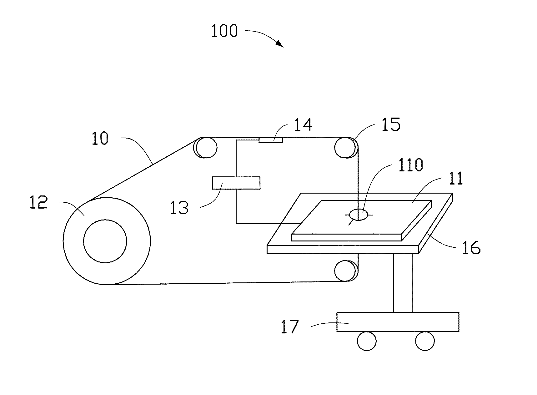
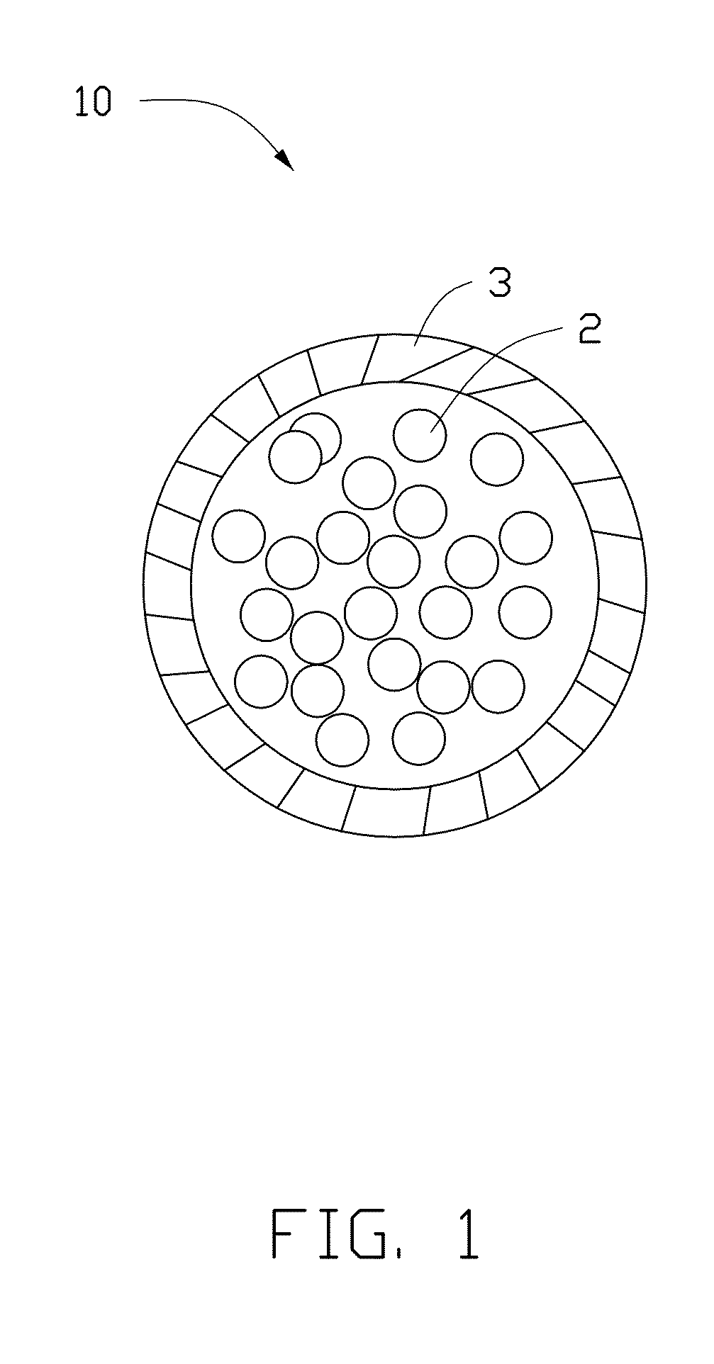
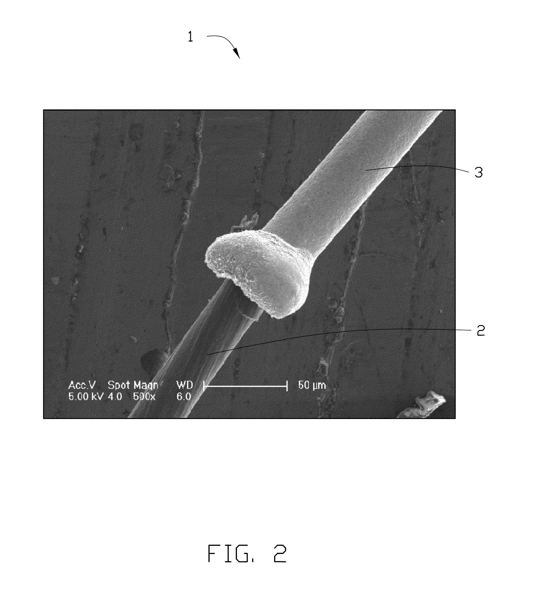
[0012]It will be appreciated that for simplicity and clarity of illustration, where appropriate, reference numerals have been repeated among the different figures to indicate corresponding or analogous elements. In addition, numerous specific details are set forth in order to provide a thorough understanding of the embodiments described herein. However, it will be understood by those of ordinary skill in the art that the embodiments described herein can be practiced without these specific details. In other instances, methods, procedures, and components have not been described in detail so as not to obscure the related relevant feature being described. Also, the description is not to be considered as limiting the scope of the embodiments described herein. The drawings are not necessarily to scale and the proportions of certain parts have been exaggerated to better illustrate details and features of the present disclosure.

[0013]Several definitions that apply throughout this disclosure...


PUM

PropertyMeasurementUnit
Lengthaaaaaaaaaa
Lengthaaaaaaaaaa
Lengthaaaaaaaaaa

Abstract

A wire cutting electrode which includes a carbon nanotube composite wire, a tensile strain rate of the carbon nanotube composite wire being less than or equal to 3%. The carbon nanotube composite wire includes a carbon nanotube wire and a metal layer. The carbon nanotube wire consists of a plurality of carbon nanotubes oriented around a longitudinal axis of the carbon nanotube composite wire. A twist of the carbon nanotube wire ranges from 10r/cm to 300r/cm. A diameter of the carbon nanotube wire ranges from 1 micron to 30 microns. The metal layer is coated on an outer surface of the carbon nanotube wire, and a thickness of the metal layer ranges from 1 micron to 5 microns. A wire cutting device using the wire cutting electrode is also provided.

Description

CROSS-REFERENCE TO RELATED APPLICATIONS[0001]This application claims all benefits accruing under 35 U.S.C. §119 from China Patent Application No. 201410164703.8, field on Apr. 23, 2014 in the China Intellectual Property Office, disclosure of which is incorporated herein by reference. The application is also related to copending applications entitled, “BINDING WIRE AND SEMICONDUCTOR PACKAGE STRUCTURE USING THE SAME”, filed ______ (Atty. Docket No. U.S. Pat. No. 56,061); “CARBON NANOTUBE COMPOSITE WIRE”, filed ______ (Atty. Docket No. U.S. Pat. No. 56,063); “HOT WIRE ANEMOMETER”, filed ______ (Atty. Docket No. U.S. Pat. No. 56,064); “DEFROSTING GLASS, DEFROSTING LAMP AND VEHICLE USING THE SAME”, filed ______ (Atty. Docket No. U.S. Pat. No. 56,065); “CONDUCTIVE MESH AND TOUCH PANEL USING THE SAME”, filed ______ (Atty. Docket No. U.S. Pat. No. 56,067); “ELECTROMAGNETIC SHIELDING MATERIAL AND CLOTHING USING THE SAME”, filed ______ (Atty. Docket No. U.S. Pat. No. 56,068); “MASS FLOWMETER”...

Claims


Application Information

Patent Timeline
IPC IPC(8): B23H7/08
CPCB23H7/08
Inventor QIAN, LIWANG, YU-QUAN
Owner BEIJING FUNATE INNOVATION TECH
Why Eureka
Try Eureka