

Mirror drive device and driving method thereof
- Summary
- Abstract
- Description
- Claims
- Application Information
AI Technical Summary
Benefits of technology
Problems solved by technology
Method used
Image

Examples
first embodiment
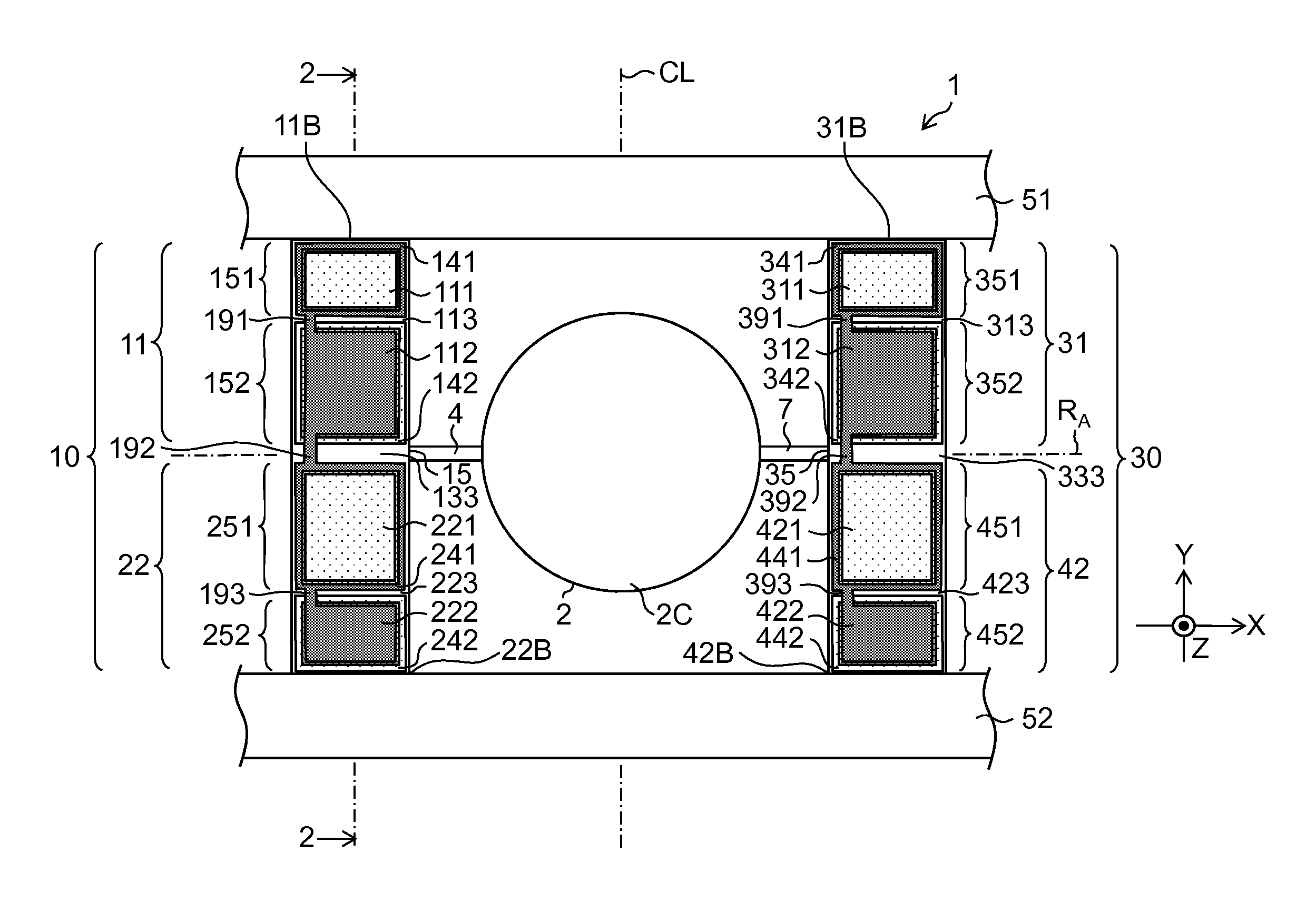
[0074]FIG. 1 is a plan view of a structure of a micro scanner device according to a first embodiment. In this example, in a plan view, a micro scanner device 1 that corresponds to “mirror drive device” includes a mirror section 2 having a circular shape, a first torsion bar section 4 and a second torsion bar section 7 that support the mirror section 2 from both sides of the diameter direction, a first actuator section 11 and a second actuator section 22 that are connected to the first torsion bar section 4 and operate as a piezoelectric actuator section 10, a third actuator section 31 and a fourth actuator section 42 that are connected to a second torsion bar section 7 and operate as a piezoelectric actuator section 30.
[0075]The first actuator section 11 and the second actuator section 22 are connected to each other through a coupling section 15, and the first torsion bar section 4 is connected to the coupling section 15. Similarly, the third actuator section 31 and the fourth actua...
utility example 1
(Utility Example 1)
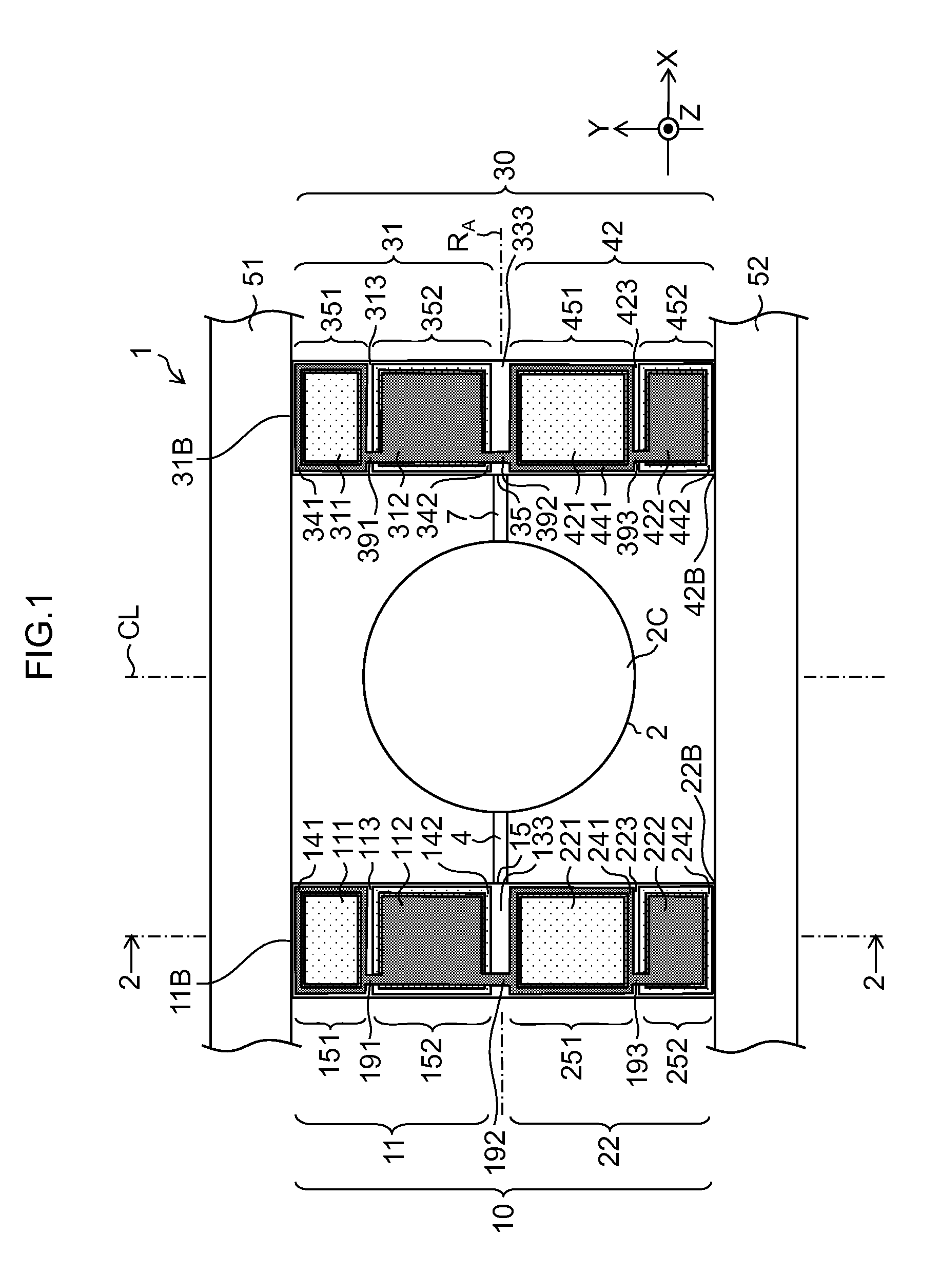
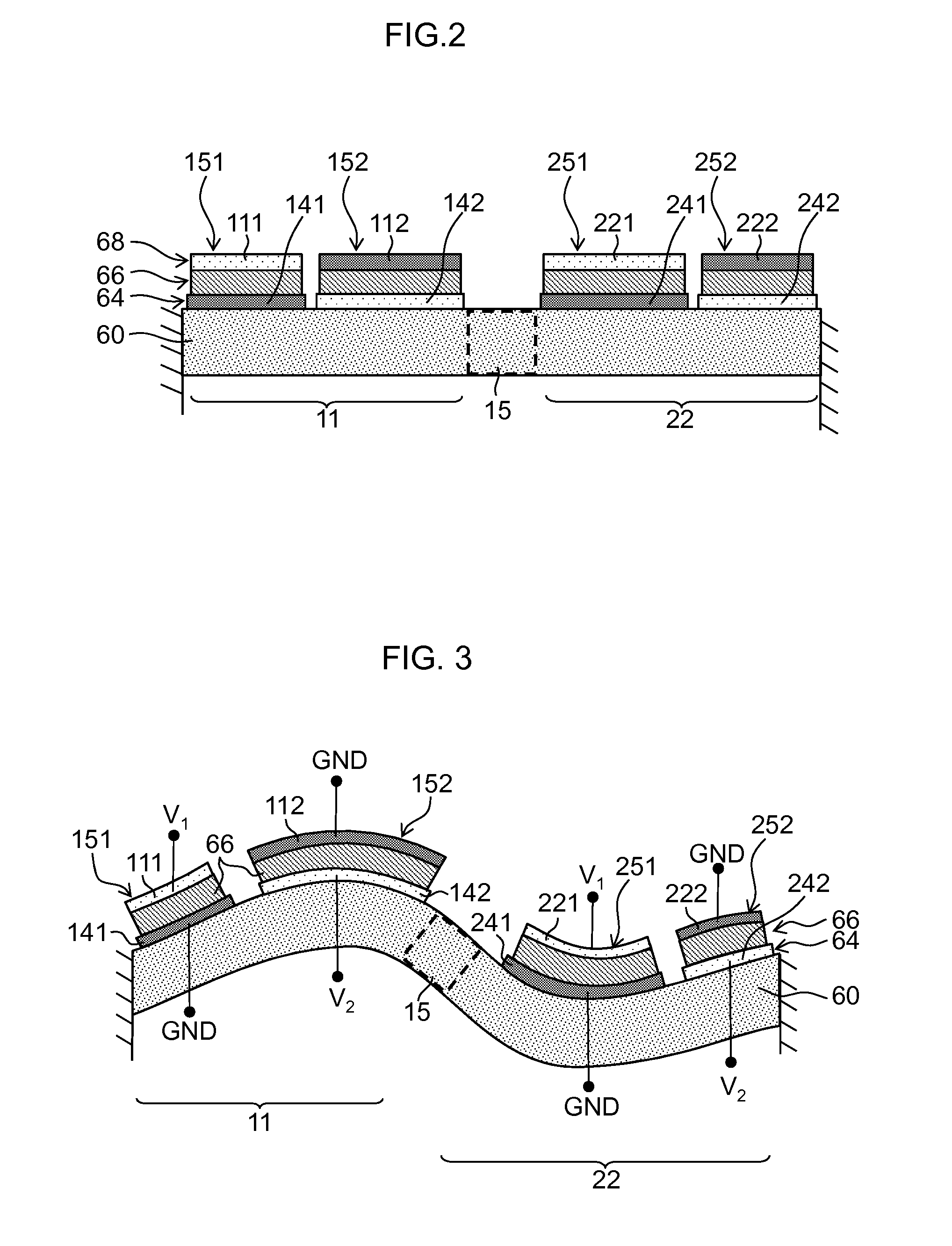
[0148]FIG. 7 is a diagram illustrating an example in which all of the first piezoelectric conversion section 151 to the eighth piezoelectric conversion section 452 are used as driving electrodes. A portion in which the piezoelectric body 66 lies between each of the electrode sections (111, 112, 221, 222, 311, 312, 421, and 422) as the upper electrode 68 and each of the electrode sections (141, 142, 241, 242, 341, 342, 441, and 442) as the lower electrode 64 operates as a piezoelectric element section. In this example, all of the electrode sections are used as driving electrodes, and all of the piezoelectric conversion sections 151, 152, 251, 252, 351, 353, 451, and 452 function as driving force generation sections.
[0149]In this case, for example, as illustrated in FIG. 7, in the first piezoelectric conversion section 151 of the first actuator section 11, the third piezoelectric conversion section 251 of the second actuator section 22, the fifth piezoelectric conve...
utility example 2
(Utility Example 2)
[0154]FIG. 8 is a diagram illustrating an example of a part the first piezoelectric conversion section 151 to the eighth piezoelectric conversion section 452 is used as a sensing (detection) electrode for stress detection. Here, an example is described in which the fourth piezoelectric conversion section 252 and the eighth piezoelectric conversion section 452 are used as sensor sections, and the fourth lower electrode section 242 and the eighth lower electrode section 442 are used as detection electrodes, the other piezoelectric conversion sections are used as driving force generation sections.
[0155]The detection electrode is set at a floating potential and detects voltage that is generated by a piezoelectric effect of the piezoelectric body 66 (positive piezoelectric effect). In FIG. 8, electrodes represented by “s” (reference numerals 242 and 422) are detection electrodes that are used to detect a sensing signal and are set at a floating potential.
[0156]As descr...
PUM
 Abstract
Description
Claims
Application Information