
Lens driving apparatus, lens barrel and optical apparatus

a technology of lens barrel and driving apparatus, which is applied in the direction of instruments, printers, cameras, etc., can solve the problems of obstructing the rotation of the motor, affecting the optical property, and the tilt of the lens group and the rotation blur, so as to achieve the effect of stably energizing the lens group without increasing the rotation load of the motor

Active Publication Date: 2015-10-29
CANON KK
View PDF3 Cites 4 Cited by
  • Summary
  • Abstract
  • Description
  • Claims
  • Application Information

AI Technical Summary

Benefits of technology

The present invention is about a device that drives a lens without causing excessive motor rotation, which can lead to tilting and blurring. The invention controls the lens group so that it is stable without causing any problems.

Problems solved by technology

However, in the conventional arts disclosed in the aforementioned patent documents, there is a possibility that a stable balance cannot be configured when, for example, an attitude is changed in a case where the mass of the lens group is large, thereby to cause a tilt of the lens group and the rotation blur.
Additionally, it may affect an optical property, for example, an image shake, as a result.
Accordingly, there is a problem in which a load that obstructs the rotation of the motor becomes high in many cases.
Although the disclosure of Japanese Patent Application Publication No. 2007-298718 enables decreasing the load to the motor compared with the disclosure of Japanese Patent Application Publication No. 6-174992, both disclosures require increasing the energizing force of the rack according to the increase of the mass of the lens group, and thus, it is difficult to avoid the similar problem to be solved.

Method used


Image

  • Lens driving apparatus, lens barrel and optical apparatus
  • Lens driving apparatus, lens barrel and optical apparatus
  • Lens driving apparatus, lens barrel and optical apparatus

Examples


first embodiment

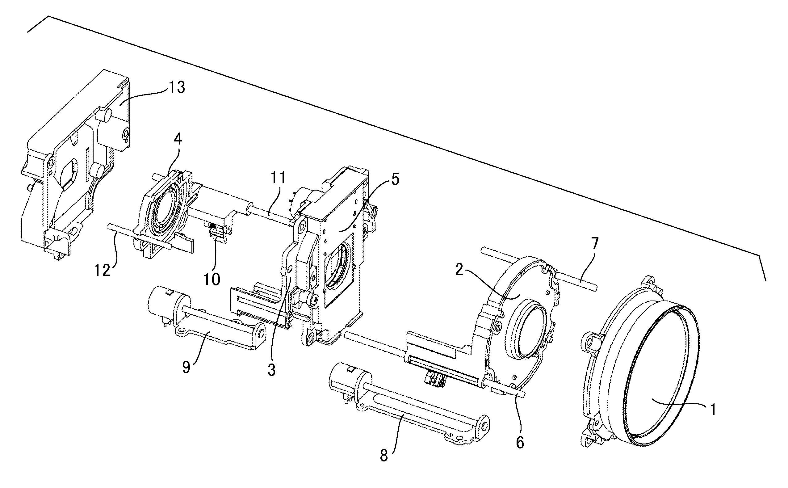
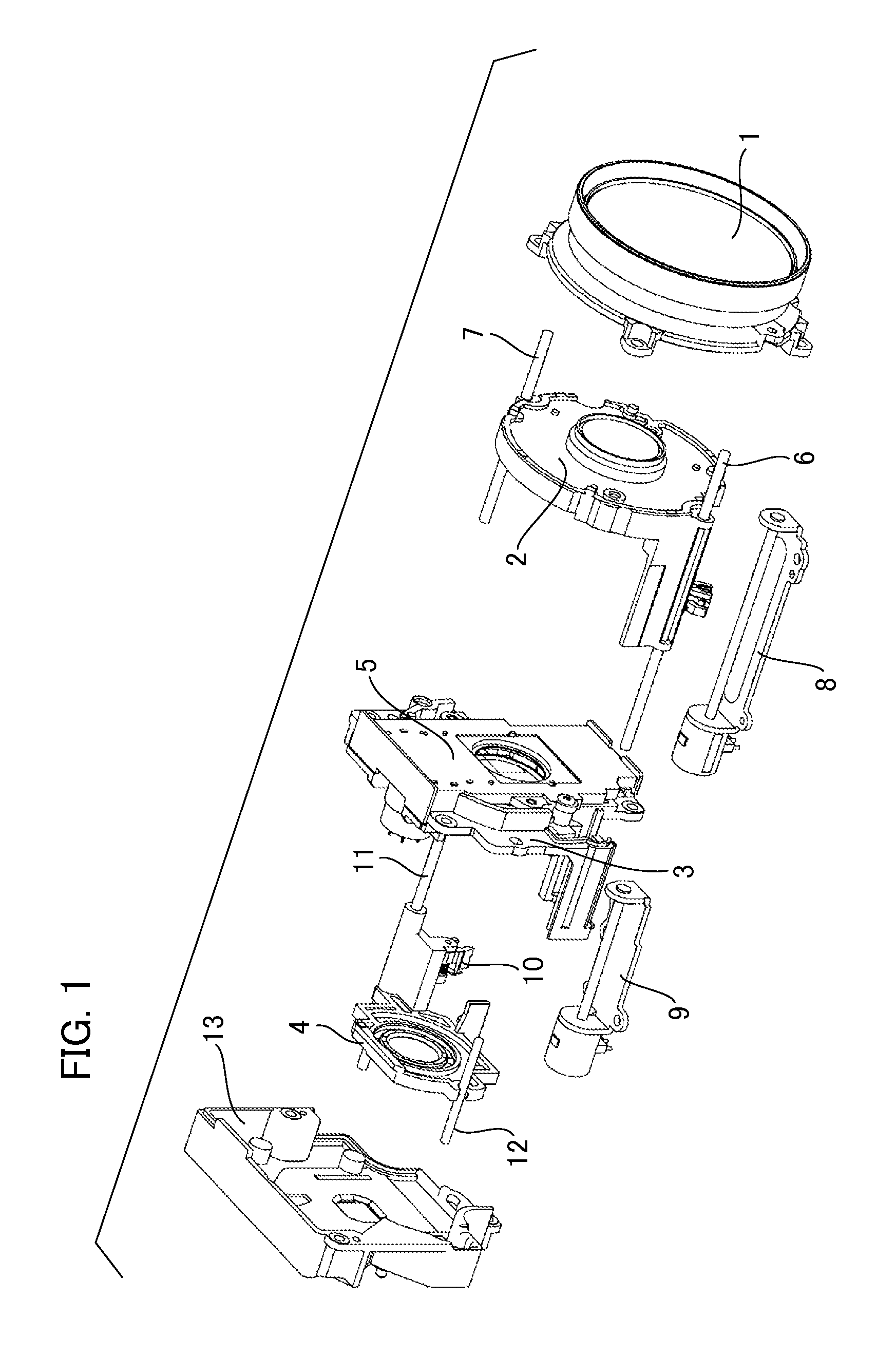
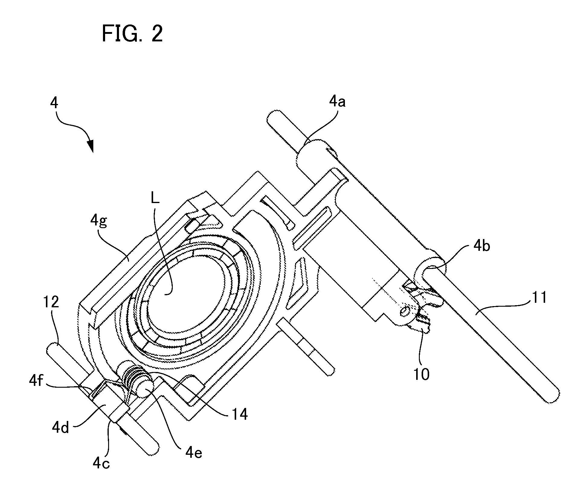
[0017]First, a description will be given of a lens barrel (lens device) that can mount a lens driving apparatus according to first embodiment of the present invention. FIG. 1 is an exploded perspective view that illustrates a configuration of a lens barrel according to first embodiment, and a fixed cylinder that fixes each of components is not illustrated for the purpose of simplifying the description. The lens barrel according to the present embodiment is an interchangeable lens that is attachable to and detachable from an image capturing apparatus (optical apparatus), for example, a digital still camera provided with an imaging element or a still camera using a silver film, in one example. However, the lens barrel according to the present embodiment may be one that is incorporated in the image capturing apparatus, not limited to being incorporated in the image capturing apparatus, and it may be, for example, an interchangeable lens that is attachable to and detachable from a proje...

second embodiment

[0021]Next, a description will be given of the lens driving apparatus according to second embodiment of the present invention. Although a spring is used as the energizing member in the first embodiment, the lens driving apparatus according to the present embodiment differs from the first embodiment in that a magnet (Mg, magnetic material) is used as the energizing member. Note that, a configuration of the lens barrel itself in the present embodiment is basically similar to that in the first embodiment, and except for the parts related to the lens driving apparatus, the detailed description is omitted.

[0022]Here, a description will be given of a configuration of the lens driving apparatus according to the second embodiment of the present invention with reference to FIG. 4. The lens driving apparatus of the present embodiment includes the focusing lens group 4, the rack 10, the guide bar 11 (first guide part), the guide bar (second guide part), and a magnet 15 (energizing member, magn...


PUM


Abstract

The lens driving apparatus includes a lens holding member that holds lens; a rack provided in the lens holding member transmits a motor driving force to the lens holding member; a first guide part that supports the lens holding member to be movable back and forth in an optical axis direction of the optical lens; a second guide part that supports the lens holding part to be movable as a first guide part, farther separated from the rack than the first guide part in a direction orthogonal to the optical axis direction; both contact parts in the lens holding part, with which both guide parts respectively are in contact; and an energizing part that energizes the second contact part at a position separated in the longitudinal direction of the second guide part so as to be in contact with the second guide part.

Description

BACKGROUND OF THE INVENTION[0001]1. Field of the Invention[0002]The present invention relates to a lens driving apparatus, a lens barrel, and an optical apparatus.[0003]2. Description of the Related Art[0004]Conventionally, a lens driving apparatus that moves a lens group by using a stepping motor when performing a variable power operation and a focusing operation has been mounted on a lens barrel used as an interchangeable lens or the like in an optical apparatus, for example, a digital still camera and a video camera. Such a lens driving apparatus that moves a guide that guides a movement of the lens during moving back and forth of the lens and a lens holding frame without a wobble between them is desired. Japanese Patent Application Publication No. 6-174992 discloses a configuration in which a regulation of a rotation blur is achieved by a rack configuration that has interposing teeth that interpose a motor screw in a rack. Additionally, Japanese Patent Application Publication No...

Claims


Application Information

Patent Timeline
Patent Type & Authority Applications(United States)
IPC IPC(8): G03B13/34G02B7/04
CPCG02B7/04G03B13/34G03B3/10
Inventor SATO, KOJI
Owner CANON KK
Learn More