
Cogeneration system for biomass gasifier

A technology of combined cooling and power generation and gasification furnace, which is applied in the direction of refrigerators, refrigeration components, refrigeration and liquefaction, etc. It can solve the problems of low utilization rate of industrial waste heat energy, affect engine performance, and high operating pressure, so as to improve system reliability performance, stable energy supply, improved combustion and cleaning effect

Active Publication Date: 2021-02-02
安徽省智慧产业研究院股份有限公司 +1
View PDF13 Cites 0 Cited by
  • Summary
  • Abstract
  • Description
  • Claims
  • Application Information

AI Technical Summary

Problems solved by technology

[0011] The purpose of the present invention is to provide a biomass gasifier cogeneration system to solve the problem of the high operating pressure of the current biomass gasifier cogeneration system and the presence of direct current in the system that affects the performance of the engine. , Occupy a large space and the energy utilization rate of the system for industrial waste heat is not high

Method used


Image

  • Cogeneration system for biomass gasifier
  • Cogeneration system for biomass gasifier
  • Cogeneration system for biomass gasifier

Examples


Embodiment 1

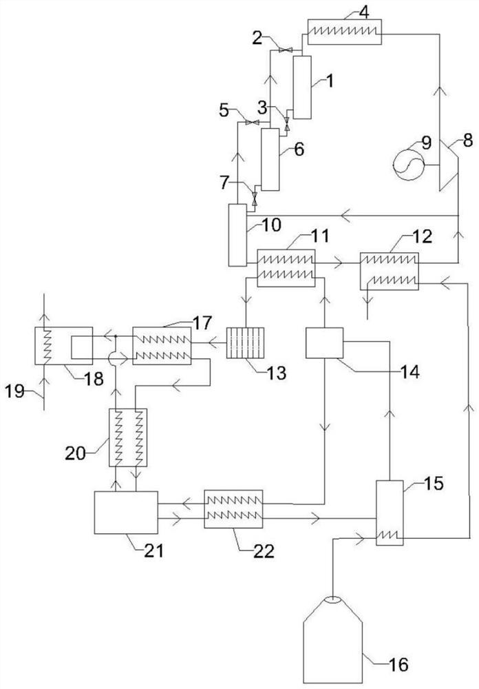
[0034]A biomass gasifier combined cooling and power system, such asfigure 1 As shown, it includes an absorption solution circulation loop, a liquid ammonia pipeline, an ammonia-helium mixture circulation loop and a pump-less organic Rankine cycle power generation mechanism. The system includes a liquid storage tank I1, a solenoid valve I2, a solenoid valve II3, a condenser I4, Solenoid valve III5, liquid storage tank II6, solenoid valve IV7, expander 8, generator 9, liquid storage tank10. Rectifier 11. Evaporator12. Condenser13. Gas-liquid separator 14, generator 15, biomass gasifier 16, liquid ammonia heat exchanger 17, evaporator18. Cold output 19, gas heat exchanger 20, absorber 21, solution heat exchanger 22; absorption solution circulation loop includes generator 15, gas-liquid separator 14, solution heat exchanger 22, liquid ammonia pipeline includes condensation Device13. Liquid ammonia heat exchanger 17, ammonia-helium mixed gas circulation loop including evaporator18. Absor...

Embodiment 2

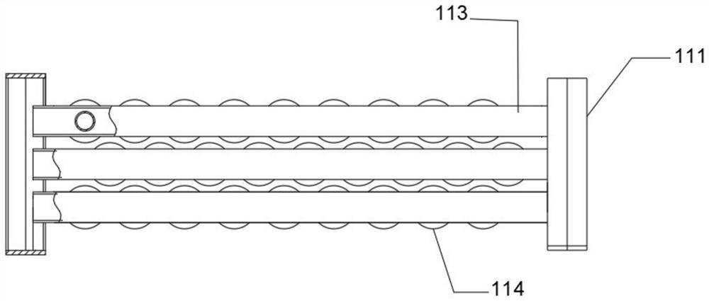
[0040]As the second embodiment of the present invention, such asfigure 2 ,image 3 withFigure 4As shown, the rectifier 11 includes two symmetrically arranged support frames 111, and a number of evenly and equidistantly arranged vent holes 112 are opened on one side of the two support frames 111, and a number of vent holes 112 are arranged between the two support frames 111. The water pipes 113 arranged evenly and equidistantly are connected with a number of evaporation fins 114 to improve the evaporation efficiency.

[0041]The specific working steps of the biomass gasifier cogeneration system of the present invention are as follows:

[0042](1) The biomass gasification furnace 16 supplies heat to the generator 15 so that the bubble pump in the generator 15 pushes the ammonia bubbles up and flows into the gas-liquid separator 14, and the liquid flows downward into the solution under the separation action of the gas-liquid separator 14 In the heat exchanger 22, the gas flows upward into the...


PUM


Abstract

The invention relates to the technical field of refrigeration equipment, in particular to a biomass gasification furnace cooling and power cogeneration system, including an absorption solution circulation loop, a liquid ammonia pipeline, an ammonia-helium mixed gas circulation loop and a pumpless organic Rankine cycle power generation mechanism, The system includes liquid storage tank I, solenoid valve I, solenoid valve II, condenser I, solenoid valve III, liquid storage tank II, solenoid valve IV, expander, generator, liquid storage tank, rectifier, evaporator, Condenser, gas-liquid separator, generator, biomass gasifier, liquid ammonia heat exchanger, evaporator, cooling output, gas heat exchanger, absorber, solution heat exchanger. The invention reduces the cost of the system and improves the reliability of the system; reduces the heat input of the whole system and improves the performance of the system; improves the combustion and ash cleaning device of the biomass gasification furnace, adds functions such as air volume control and temperature control, and makes the biomass gasify The energy supply of the furnace is more stable and efficient; the input of mechanical work is reduced, and the system efficiency is improved.

Description

Technical field[0001]The invention relates to the technical field of refrigeration equipment, in particular to a biomass gasifier combined cooling and power generation system.Background technique[0002]With the rapid development of my country's economy, the consumption of energy is increasing. A wide range of industrial activities produce a large amount of low-grade heat energy that is relatively low in temperature and difficult to recycle. The more typical ones are exhaust gas and waste residue with a temperature of about 150°C. This kind of low-grade energy has always been underutilized due to high recovery cost and technical difficulty. However, the loss of heat energy accounts for a large part of the industrial energy dissipation. Therefore, suitable technology is used to carry out such low-temperature heat sources. Recycling is of great significance for reducing industrial energy consumption and achieving sustainable development.[0003]Biomass gasifier is a kind of boiler. It use...

Claims


Application Information

Patent Timeline
Patent Type & Authority Patents(China)
IPC IPC(8): F25B41/30F25B41/40F25B43/00F25B39/00F23N5/00F01K25/14F01K27/00F01K11/00
CPCF25B41/00F25B43/00F25B39/00F23N5/00F01K25/14F01K27/00F01K11/00
Inventor 方超潘键文韩骁杰王紫璇李海玉王玉王丽伟
Owner 安徽省智慧产业研究院股份有限公司
Learn More