Method for the automatic correction of alignment errors in star tracker systems

an automatic correction and alignment technology, applied in direction finders, navigation instruments, instruments, etc., can solve the problems of not being able to mount the star tracker on a stable block, the influence of alignment errors of the viewing directions of the individual star tracker, and not being able to achieve stable block mounting, etc., to achieve the effect of improving accuracy

Inactive Publication Date: 2015-10-29
JENA-OPTRONIK
View PDF8 Cites 11 Cited by
  • Summary
  • Abstract
  • Description
  • Claims
  • Application Information

AI Technical Summary

Benefits of technology

[0006]It is an object of the present invention to provide a star tracker system for determining the orientation which exhibits improved accuracy and in which alignment errors of the star trackers that occur are automatically corrected.

Problems solved by technology

No studies have been conducted on the influence of alignment errors of the viewing directions of the individual star trackers.
Due to the different designs of flying objects, in actual practice, it is not always possible to mount the star trackers on a stable block, as a result of which the individual trackers have to be arranged at different places on the platform while maintaining the requisite viewing directions.
Alignment errors then occur primarily due to deformations caused by mechanical loads or temperature fluctuations.
In the case of large objects, the exact optical alignment can also be problematic.

Method used


Image

  • Method for the automatic correction of alignment errors in star tracker systems
  • Method for the automatic correction of alignment errors in star tracker systems
  • Method for the automatic correction of alignment errors in star tracker systems

Examples


Embodiment Construction

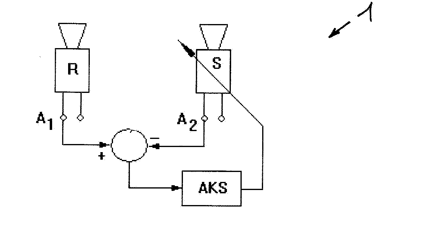
[0037]FIG. 1 also shows the tracker system 1 that has been installed in a flying object (not shown here) and that consists of two star trackers R, S. The star tracker R, which is attached to a platform (not shown here) of a flying object in a particularly stable manner, serves as the reference tracker. The star trackers R, S are aligned in different spatial directions. The output signals of the star trackers R, S, preferably in the form of quaternions, indicate the orientation of the star trackers R, S in a reference coordinate system, in the coordinate system of the reference tracker R or in a master coordinate system of the tracker system 1. If the star trackers R, S are functioning properly, approximately the same orientation data should be obtained at the outputs A1 and A2 relative to the master coordinate system. In order for the star tracker system 1 to attain its full accuracy, it is necessary to compensate for a possible misalignment of the star tracker S. For this purpose, ...


PUM


Abstract

A method for the automatic correction of alignment errors in individual star trackers (R, S) of star tracker systems (1) is provided. The correction of orientation errors is necessary whenever it is not possible to mount the star trackers of the star tracker system on a shared stable block of a platform. Orientation errors can arise due to installation deviations and deformation of the platform, for instance, caused by mechanical loads or temperature fluctuations. A star tracker (R) that is attached in a very stable manner to the platform serves as the reference tracker. The orientation that it measures constitutes the reference information. An error signal and an orientation matrix are derived from the measured orientation of the other star trackers, thereby effectuating the correction of the coordinate systems of the star trackers that are to be corrected, and thus of their measured quantities. The resulting orientation as the starting quantity of the star tracker system is then calculated on the basis of the orientation information of the reference tracker and of the other star trackers. The linking of the measured results of the individual star trackers can take place on the level of the star vectors of a star catalog, on the level of preprocessed tracker signals or on the level of the quaternions and/or on the level Euler angles.

Description

[0001]The invention relates to a method for the automatic correction of alignment errors in tracker systems consisting of several star trackers.BACKGROUND[0002]European patent application EP 1 111 402 A1 discloses a tracker system comprising three star trackers with fields of vision aligned in different directions, whereby each star tracker detects star positions and outputs them to a central evaluation unit where the orientation of the tracker system is determined and the orientation of the flying object is determined on the basis of the alignment of the tracker system with respect to a flying object. In order to avoid additional errors, the star cameras are situated on a solid block. No studies have been conducted on the influence of alignment errors of the viewing directions of the individual star trackers. Practically no alignment errors occur if the trackers are mounted on a stable block and are adjusted by means of known optical methods. The measuring accuracy of the tracker s...

Claims


Application Information

Patent Timeline
Patent Type & Authority Applications(United States)
IPC IPC(8): G06K9/00G06K9/52G06K9/62G06T7/00
CPCG06K9/00624G06K9/6201G06K9/52G06T7/004G01C21/025G01S3/7867G06T7/70G06F18/22
Inventor STRIETZEL, ROLANDMICHEL, KLAUSRATZSCH, DIETMAR
Owner JENA-OPTRONIK
Why Eureka
Try Eureka