Optimizing voltage and var on the electric grid using distributed var sources

a technology of distributed var and voltage, applied in the direction of electric variable regulation, process and machine control, instruments, etc., can solve the problems of their reliance on corrections on the primary side of distribution transformers, and their electromechanical nature of medium voltage assets (i.e., ltcs and capacitor banks)

Active Publication Date: 2015-10-29
SENTIENT ENERGY TECH LLC
View PDF7 Cites 32 Cited by
  • Summary
  • Abstract
  • Description
  • Claims
  • Application Information

AI Technical Summary

Benefits of technology

[0007]In accordance with one embodiment, a computer-implemented method for voltage and volt ampere reactive (VAR) control of a power system comprises determining a transformer voltage setpoint. Additionally, the method comprises determining voltage setpoints for a set of distributed VAR devices implemented in the power system to be equal to that of the transformer voltage setpoint to effectuate self-balancing of the power system.
[0008]In accordance with another embodiment, a system comprises a service transformer and a load coupled to the service transformer. Furthermore, the system comprises at least one distributed VAR device coupled to the load, the at least one distributed VAR device being operative in response to a voltage setpoint, wherein the voltage setpoint associated with a controllable transformer on a high-voltage or primary side.

Problems solved by technology

However, at least one drawback for each of the above-noted schemes is their reliance on corrections on the primary side of the distribution transformer.
This is either never sensed, or remains uncompensated for without any secondary side fast and dynamic Volt-VAR control devices.
Moreover, medium voltage assets (i.e., LTCs and capacitor banks) are electromechanical in nature and have limited life.
Further, capacitor banks once switched off need several minutes of discharge time before they can be re-engaged.
Due to all these limitations of primary side asset, voltage VAR control achievable through the control of primary side assets is not only sub-optimal, but is also severely limited.
Furthermore, with distributed generation (DG) such as solar photovoltaic (PV), being introduced on the grid at an ever increasing rate, the efficacy of these sparsely deployed primary assets is highly diminished.
Consequently, it would require re-visiting the placement of the primary side assets more frequently which would essentially increase operating expenditure for utilities.

Method used


Image

  • Optimizing voltage and var on the electric grid using distributed var sources
  • Optimizing voltage and var on the electric grid using distributed var sources
  • Optimizing voltage and var on the electric grid using distributed var sources

Examples


Embodiment Construction

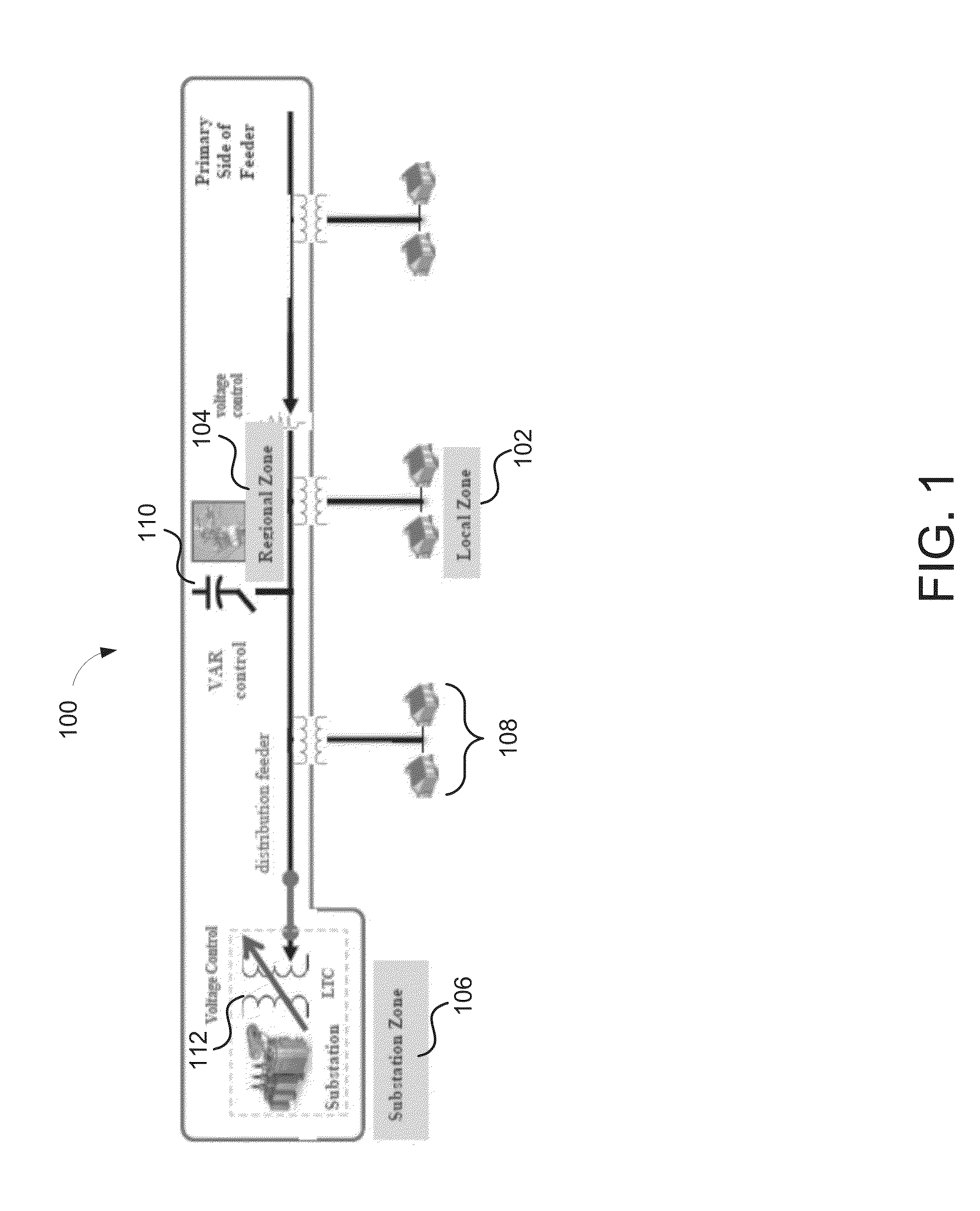
[0029]As alluded to previously, conventional voltage and VAR control relies on assets that are on the primary side of the feeder and assumes an averaged model for the devices. FIG. 1 illustrates an example power system 100 that is utilizing conventional voltage and VAR control. In the illustrated example, the power system 100 may include a local zone 102, a regional zone 104, and a substation zone 106. The local zone 102 may include customer loads 108 that may be highly variable and stochastic. As can be appreciated, there is no voltage control in the local zone 102.

[0030]The regional zone 104 may include the aforementioned switched capacitor banks 110 that provide VAR control. The control provided by the switched capacitor banks 110 may be slow and “lumpy.” For example, the switched capacitor banks 110 may be switched only, e.g., two to three times a day. Further, the response time of capacitor bank can be on the order of several seconds to minutes. Moreover, they cannot compensate...


PUM


Abstract

A plurality of edge of network grid volt ampere reactive (VAR) sources are provided in a power system in order to effectuate control at a customer level, which in turn effectuates control at a feeder level, which in turn effectuates control of an entire power system or wide area electric grid network. By optimally selecting voltage setpoints and applying such voltage setpoints to the plurality of edge of network grid VAR sources, the power system can be configured to self-balance, power factor compensation can be determined without the need for measuring load power factor. Moreover, traditionally volatile voltages at the feeder can be flattened, and VAR control can be realized.

Description

CROSS-REFERENCE TO RELATED APPLICATIONS[0001]The present application claims the benefit of U.S. Provisional Patent Application No. 61 / 983,634 filed Apr. 24, 2014, which is incorporated herein by reference in its entirety.FIELD[0002]Various embodiments generally relate to voltage and volt-ampere reactive power (VAR) management along transmission and distribution network. More particularly, various embodiments are related to controlling end consumer, feeder, and / or system-wide voltage and VAR levels using distributed VAR sourcesDESCRIPTION OF THE RELATED ART[0003]A primary purpose of voltage control is maintaining acceptable voltage (e.g. in the United States, as per the American National Standards Institute (ANSI) band, the voltage at the service entrant is to be maintained between 120 volts plus or minus five percent) at the service entrance of customers served by a feeder under all possible operating conditions. Electric utilities traditionally maintain distribution system voltage ...

Claims


Application Information

Patent Timeline
Patent Type & Authority Applications(United States)
IPC IPC(8): H02J3/18
CPCH02J3/18Y02E40/30
Inventor DIVAN, DEEPAKRAJMOGHE, ROHIT
Owner SENTIENT ENERGY TECH LLC
Why Eureka
Try Eureka