Eureka AIR delivers breakthrough ideas for toughest innovation challenges, trusted by R&D personnel around the world.

Methods and apparatus for noise attenuation in an engine nacelle

a technology of engine nacelle and noise attenuation, which is applied in the direction of non-positive displacement fluid engines, liquid fuel engine components, flooring insulations, etc., can solve the problems of limited linearity and thus acoustic performance of at least some known facesheets, prohibitive time required to form more of the small perforations with the necessary precision, and significant increases the cost and time required for the manufacture of septumized honeycomb materials

Active Publication Date: 2015-11-05
THE BOEING CO
View PDF9 Cites 47 Cited by
  • Summary
  • Abstract
  • Description
  • Claims
  • Application Information

AI Technical Summary

Benefits of technology

The patent text describes an acoustic liner used in a nacelle for an engine. The acoustic liner has two cores, each with cells defined by walls. The first core has a thicker thickness than the second core. The acoustic liner also has a second fabric sheet between the two cores. The nacelle also includes a structural inner barrel that has a third core with cells defined by walls. The acoustic liner is coupled to the structural inner barrel. The technical effect of the invention is to provide an improved design for the acoustic liner that reduces noise and improves the quality of the engine's sound.

Problems solved by technology

However, the linearity, and thus the acoustic performance, of at least some known facesheets is limited because a cost and a time required to form more of the small perforations with a necessary precision is prohibitive.
Thus, to form a septumized core, a segment of septum material must be inserted, positioned, and secured individually within each full depth cell, which significantly increases a cost and time required to manufacture the septumized honeycomb material.
Furthermore, in at least some known acoustic core materials, the backsheet does not substantially contribute to the strength of the acoustic core material.

Method used


Image

  • Methods and apparatus for noise attenuation in an engine nacelle
  • Methods and apparatus for noise attenuation in an engine nacelle
  • Methods and apparatus for noise attenuation in an engine nacelle

Examples


Embodiment Construction

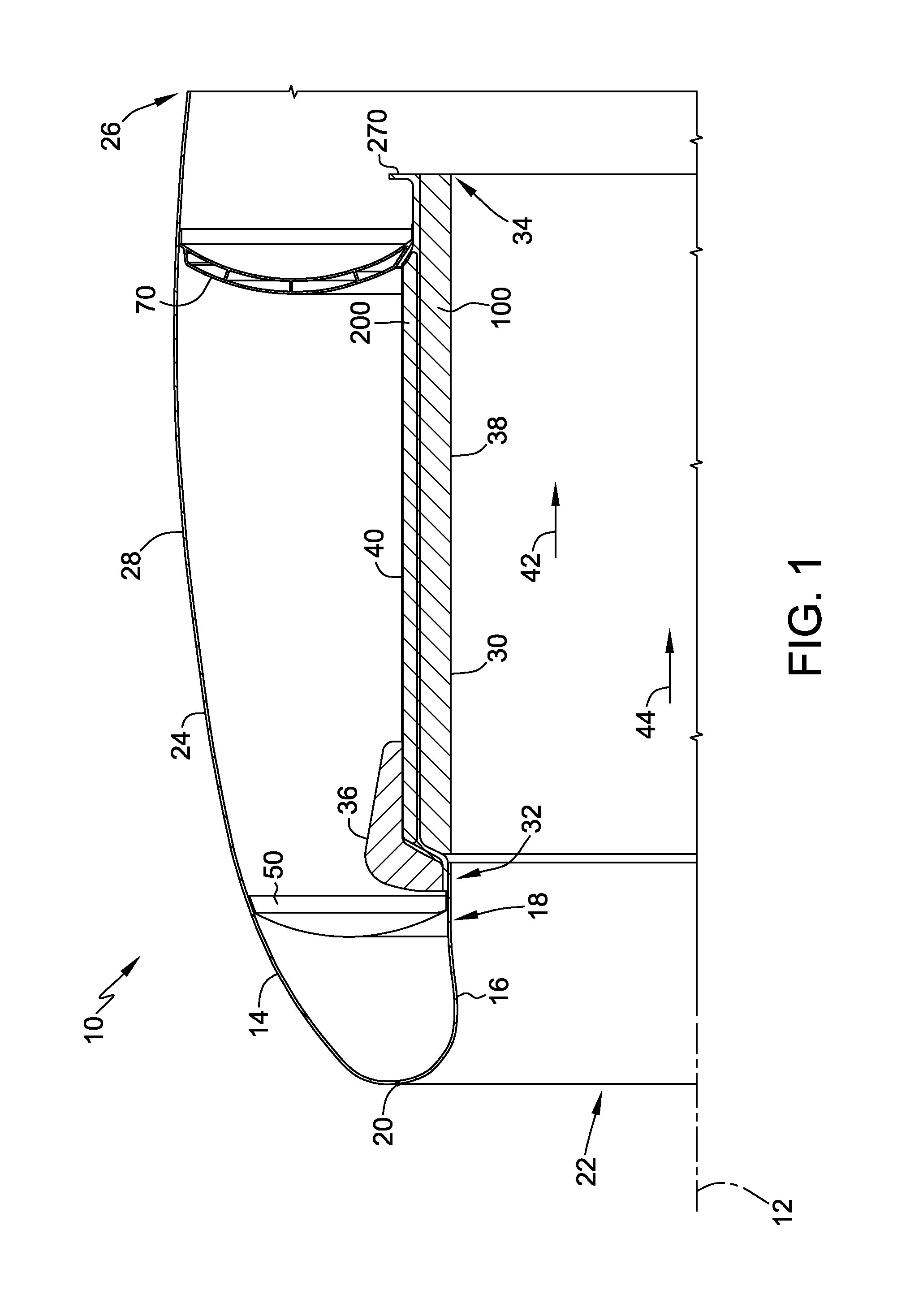
[0014]The apparatus and methods described herein provide for a lightweight and efficient engine nacelle that attenuates noise promulgating from the engine while also providing increased structural rigidity. The engine nacelle includes a lipskin assembly comprising a lipskin that includes a first segment and a second segment that are coupled together at a location proximate to a hilite of the nacelle. The second segment extends sufficiently far downstream to reduce or eliminate a need for at least one closeout panel aft of the lipskin. In addition to separately formed first and second segments, the embodiments provide for superplastic, or alternatively non-superplastic, stretch-forming of the first and second segments to facilitate reducing or eliminating ripples and / or waves in the lipskin. As such, the lipskin described herein unexpectedly reduces or eliminates a premature transition from natural laminar air flow to turbulent air flow as compared to conventional lipskins.

[0015]Moro...


PUM

PropertyMeasurementUnit
Porosityaaaaaaaaaa
Thicknessaaaaaaaaaa
Diameteraaaaaaaaaa

Abstract

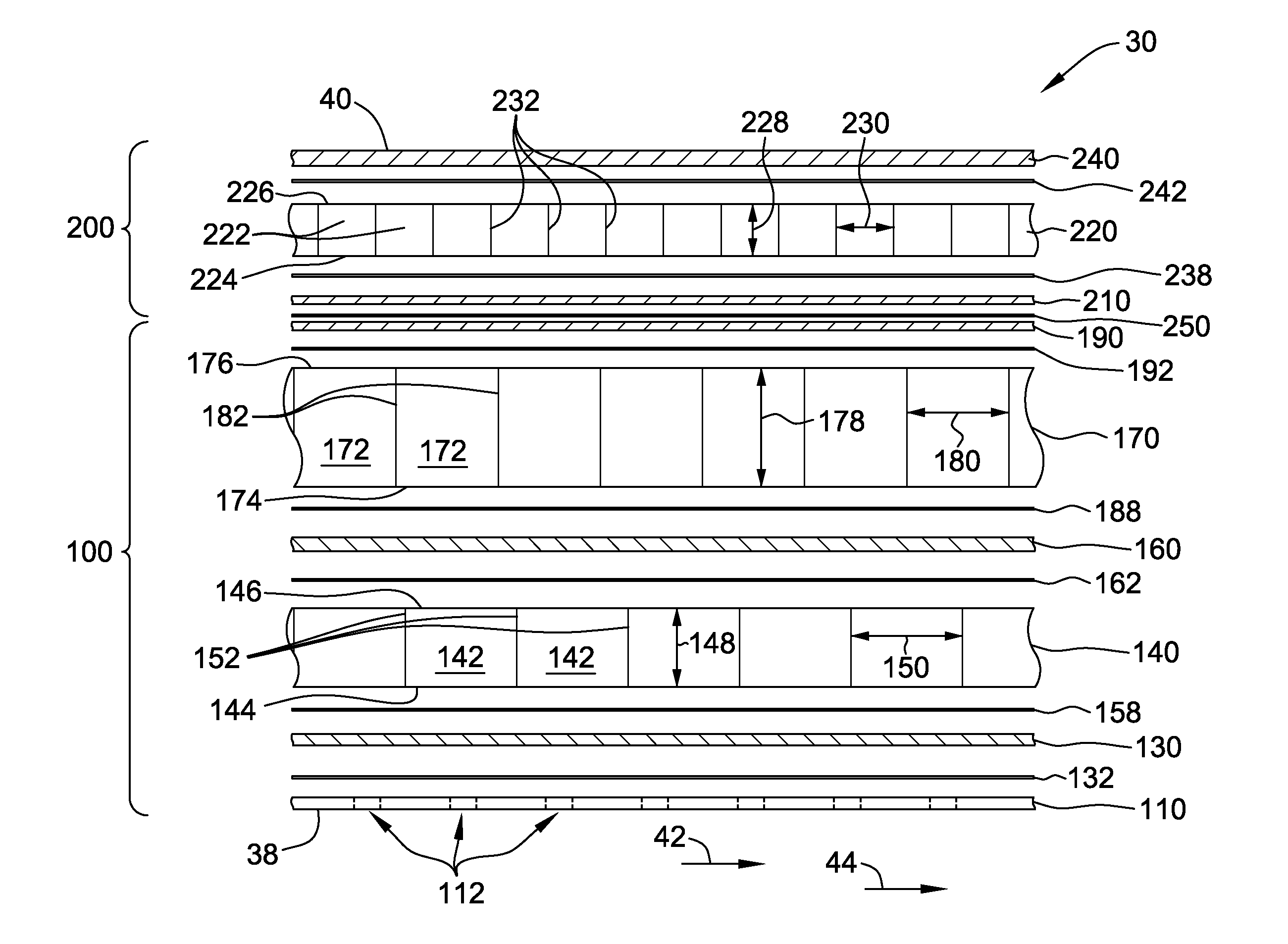
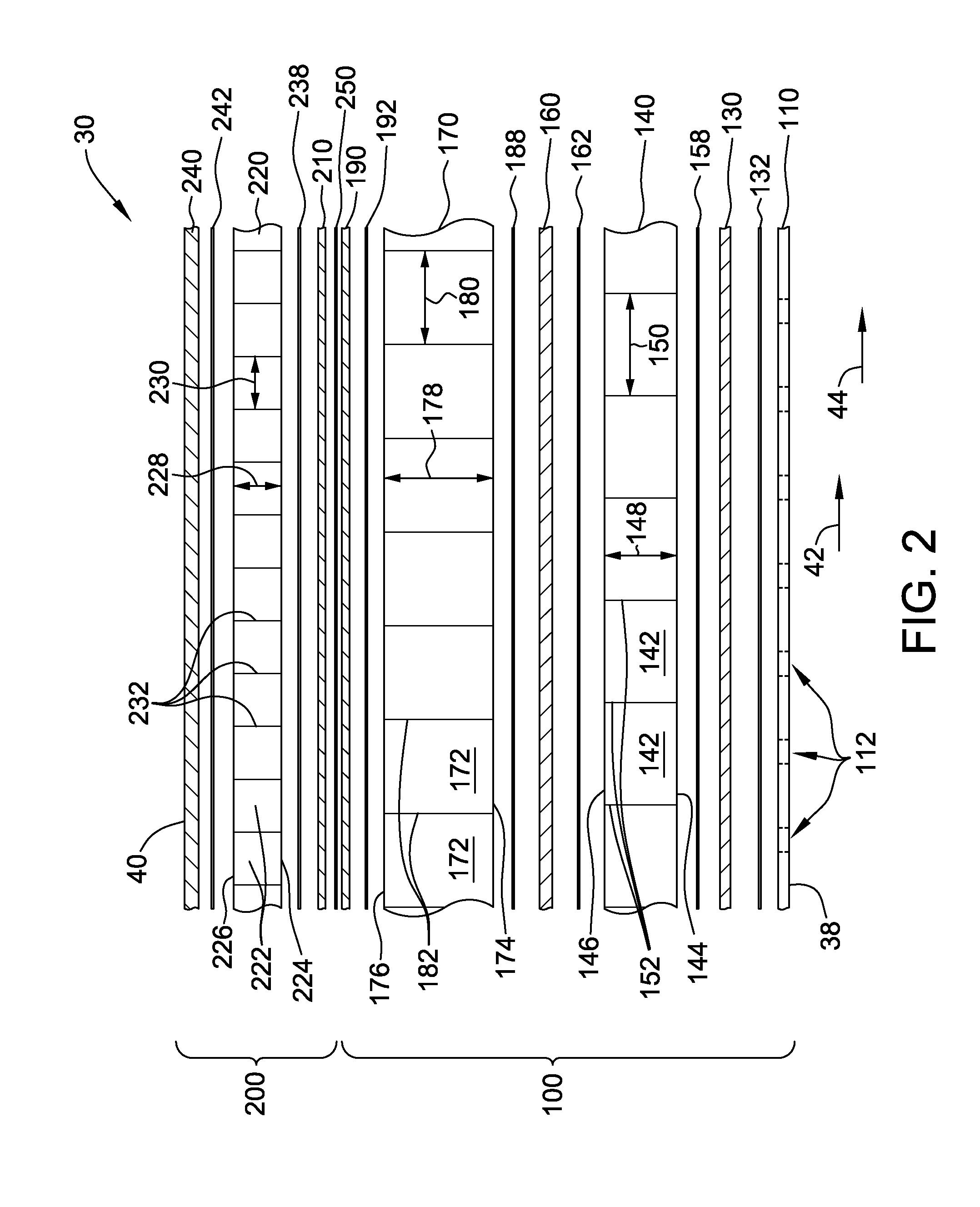
An acoustic liner includes a first core that has a plurality of first core cells defined by a corresponding plurality of first core cell walls. The first core has a first core thickness. The acoustic liner also includes a second core that has a plurality of second core cells defined by a corresponding plurality of second core cell walls. The second core has a second core thickness, and the first core thickness and the second core thickness are unequal. The acoustic liner further includes a second fabric sheet coupled between the first core and the second core. Each of the plurality of second core cell walls generally is not coplanar with any of the plurality of first core cell walls.

Description

BACKGROUND[0001]The field of the disclosure relates generally to noise attenuation, and, more particularly, to methods and apparatus for attenuating noise in an engine nacelle.[0002]At least some known engines, such as some known jet engines and turbofan jet engines, are surrounded by a generally barrel-shaped nacelle. At least some known nacelles include an inner barrel in which an acoustic core material provides both structural strength and noise attenuation for the nacelle. For one example, at least one known acoustic core material includes a honeycomb core, a perforated facesheet coupled to an inboard side of the core, and a backsheet coupled to an outboard side of the core. Sound waves generated inside the engine enter the cells of the core through the facesheet and reflect from the backsheet at a phase different from the entering sound waves, which tends to cancel out the incoming sound waves.[0003]Moreover, at least some known acoustic core materials include an approximately ...

Claims


Application Information

Patent Timeline
IPC IPC(8): F02C7/24B32B5/02B32B37/12
CPCF02C7/24B32B37/12B32B5/02Y10T156/10B32B2250/03B32B2307/102B32B2597/00F05D2260/96B32B37/146B32B2605/18B32B38/1833F02C7/045F05D2250/283F02K1/827B64D2033/0206F01D25/24F05D2220/36F05D2230/60G10K11/161
Inventor LUMBAB, ALEX C.LEISTEN, BRADLEY SCOTT
Owner THE BOEING CO
Why Eureka
Eureka Blog
Learn More