Communication apparatus and packet transfer method

a technology of communication apparatus and packet transfer, applied in the field of communication apparatus, can solve the problems of short storage capacity, inability to handle problems, limited storage capacity of reception terminal and transmission terminal, etc., and achieve the effect of improving retransmission efficiency

Inactive Publication Date: 2015-11-05
HITACHI LTD
View PDF1 Cites 2 Cited by
  • Summary
  • Abstract
  • Description
  • Claims
  • Application Information

AI Technical Summary

Benefits of technology

[0007]In WO 2012 / 066824 A1, retransmission efficiency is improved by using a NACK for a retransmission request. However, in a case where a NACK is used, the communication terminals on both the transmission side and the reception side need to support the communication method disclosed in WO 2012 / 066824 A1. Meanwhile, actual network includes not only terminals supporting the communication method disclosed in WO 2012 / 066824 A1 but also terminals using a common communication method. This means that communication based on a common communication method also occurs.
[0011]Therefore, it is an object of this invention to efficiently retransmit discarded packets and to reduce discarded location storage capacity.
[0013]According to the representative embodiment of this invention, the amount of discarded location information can be reduced, and the data transfer throughput can be improved. Problems, configurations, and effects other than those described above are made clear based on the following description of embodiments.

Problems solved by technology

However, in high-speed communication, the following problems occur, and such problems cannot be handled by the method defined in RFC 3517.
Depending on the implementation method, the storage capacity of the reception terminal and the transmission terminal may be limited.
Therefore, when the amount of discards becomes a predetermined amount or more, the reception terminal may be short of storage capacity, which may prevent newly transmitted packets from being received.

Method used


Image

  • Communication apparatus and packet transfer method
  • Communication apparatus and packet transfer method
  • Communication apparatus and packet transfer method

Examples


first embodiment

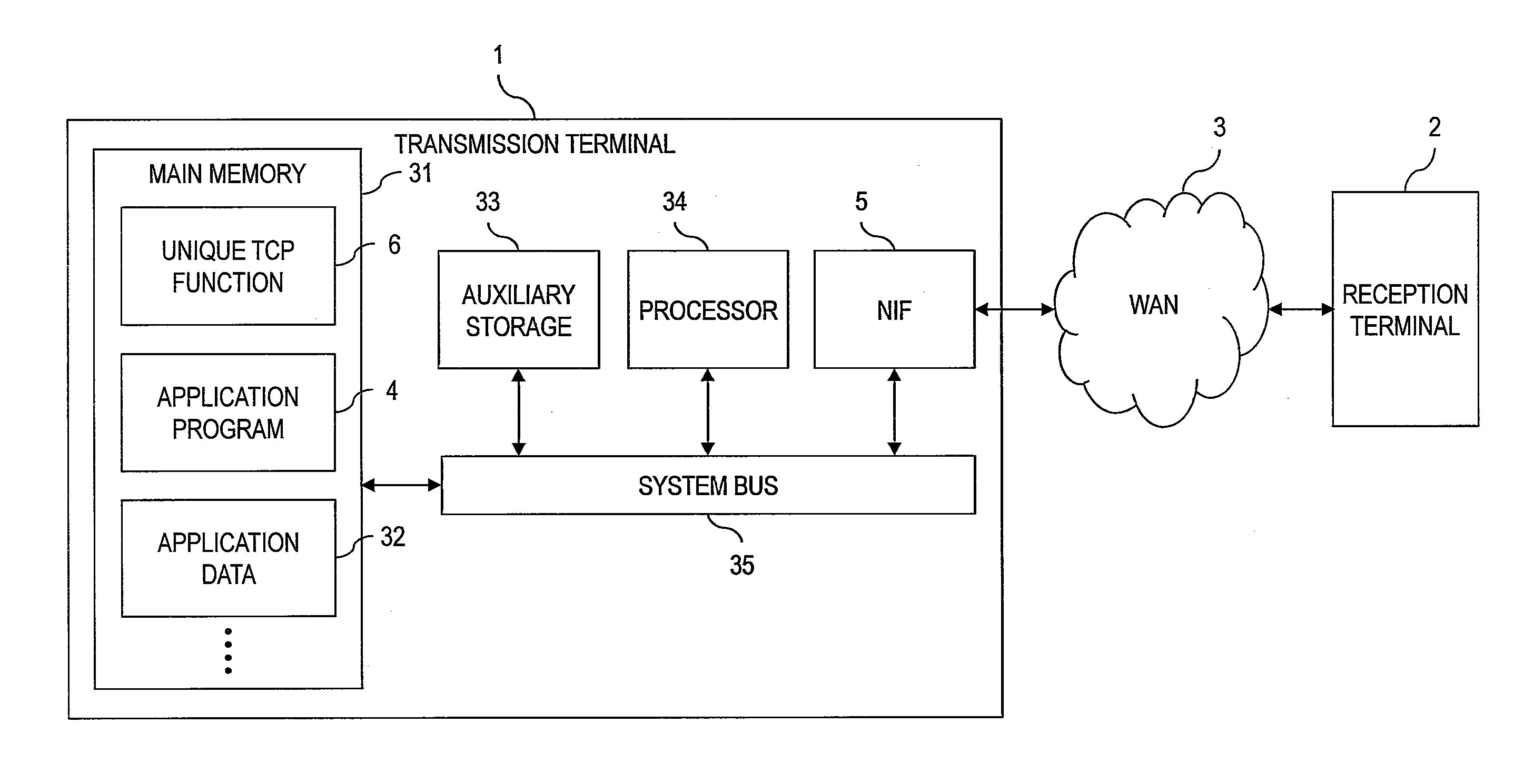
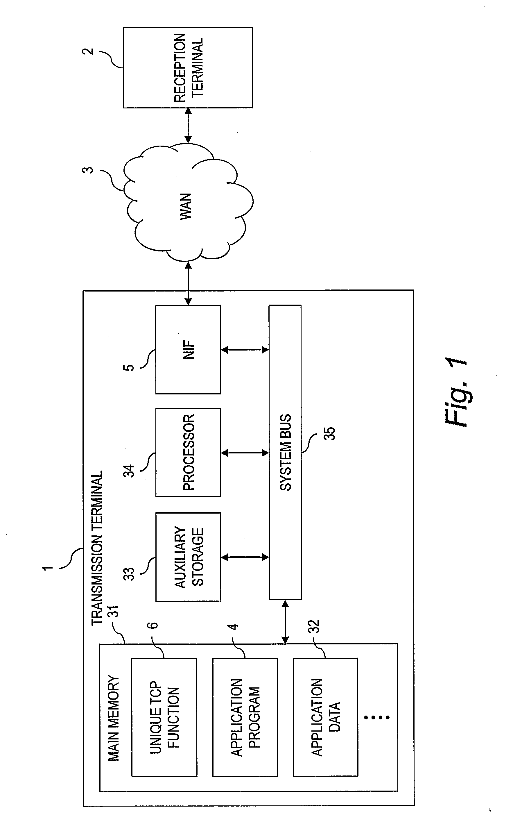
[0032]FIG. 1 is a diagram for illustrating a configuration of a system according to a first embodiment of this invention.

[0033]The system according to the first embodiment includes a transmission terminal 1, a WAN 3, and a reception terminal 2.

[0034]The transmission terminal 1 includes at least a network interface (NIF) 5, a main memory 31, an auxiliary storage 33, a processor 34, and a system bus 35 coupling each of those devices to each other for transferring data. The main memory 31 temporarily stores programs and data. The auxiliary storage 33 stores programs and data. The processor 34 is configured to execute programs stored in the main memory 31.

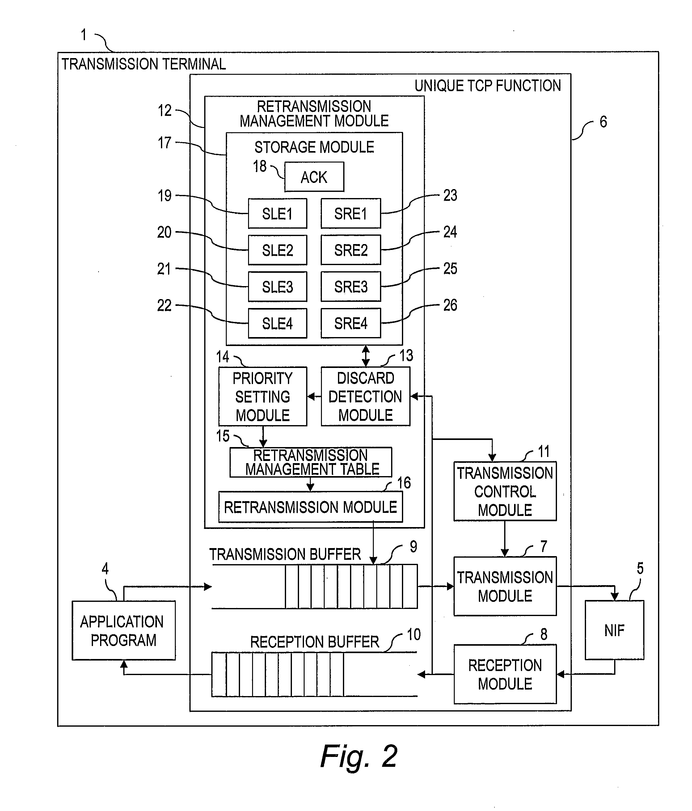
[0035]The main memory 31 stores a program for a unique TCP function 6, an application program 4, application data 32, and the like.

[0036]The auxiliary storage 33 is, for example, a non-volatile storage device such as a flash memory or a magnetic storage device. The auxiliary storage 33 stores programs to be executed by the processor 34...

second embodiment

[0079]In a second embodiment of this invention, a method of setting the priority in a different manner from that in the first embodiment is described.

[0080]In the first embodiment, only retransmission blocks having one packet are retransmitted, but in the second embodiment, blocks having more than one packet (e.g., 2 or 3 packets) are also retransmitted. However, because the priority of blocks having a smaller number of packets is set higher, blocks having one packet are retransmitted first. In a case where packets are consecutively discarded, the method according to the second embodiment is effective. It should be noted that in the second embodiment, only the differences from the above-mentioned first embodiment are described. Configurations and processes that are the same as in the first embodiment are denoted with the same reference numerals, and a description thereof is omitted here.

[0081]FIG. 10 is a function block diagram of the retransmission management module 12 according to...

third embodiment

[0091]In a third embodiment of this invention, a method of detecting a shortage in the storage capacity in a different manner from that in the first embodiment is described.

[0092]In the first embodiment, for some reason, in a case where an ACK packet is received in which all of the SACKs duplicate those of the immediately previous ACK, it may be mistakenly determined that a storage capacity shortage has occurred in the reception terminal 2. Such a phenomenon occurs when, for example, the reception terminal 2 sends a notification that the same packet has been received to the transmission terminal 1 with the same SACK in a case where the reception terminal 2 is employing the standard method defined in RFC 2883, if the same packet as a packet that has already been received is again received. At this point, after the transmission terminal 1 retransmitted the packet already received by the reception terminal 2, the transmission terminal 1 has retransmitted the same packet due to a time o...


PUM


Abstract

To efficiently retransmit discarded packets and to reduce discarded location storage capacity, it is provided a communication apparatus to be coupled to a network, the communication apparatus being configured to: transmit data to a correspondent communication apparatus coupled to the network; receive an acknowledgement transmitted from the correspondent communication apparatus; monitor whether or not a storage capacity shortage for storing discarded locations of transmitted data in the correspondent communication apparatus; and retransmit data by setting a retransmission priority for discarded locations in a case of the storage capacity shortage.

Description

INCORPORATE BY REFERENCE[0001]The present application claims priority from Japanese patent application JP 2013-015245 filed on Jan. 30, 2013, the content of which is hereby incorporated by reference into this application.BACKGROUND OF THE INVENTION[0002]This invention relates to a communication apparatus.[0003]In cloud computing, a user uses the computer resources of an external data center rather than those at the location where he / she is present. The data center stores data to be used by the user, and hence the data is frequently transferred between the user's location and the data center.[0004]Data centers are located widely around the world, and in some cases may not be in the same country as the user's location. For example, it is common to utilize an overseas data center having low usage charges.[0005]When utilizing an overseas data center, the data transfer rate may be slow. For communication to / from a distant data center, the round trip time (RTT), which is the time from a p...

Claims


Application Information

Patent Timeline
Patent Type & Authority Applications(United States)
IPC IPC(8): H04L1/08H04L29/06H04L12/823H04L47/32
CPCH04L1/08H04L69/163H04L47/323H04L1/1877H04L1/1887
Inventor OISHI, YUJIISOBE, TAKASHIYAZAKI, TAKEKI
Owner HITACHI LTD
Why Eureka
Try Eureka