Eureka AIR delivers breakthrough ideas for toughest innovation challenges, trusted by R&D personnel around the world.

Systems and methods for molding

Inactive Publication Date: 2015-11-12
TOYOTA MOTOR EUROPE
View PDF1 Cites 6 Cited by
  • Summary
  • Abstract
  • Description
  • Claims
  • Application Information

AI Technical Summary

Benefits of technology

The patent describes a method for creating plastic parts with different thicknesses without using a complicated mold or excessive time. The mold has two zones with different thermal conductivity, which allows the material to solidify in certain locations and expand in others. This results in a thicker part without adding extra weight or holding pressure. The material is provided to the mold in a calculated amount to ensure complete filling without the need for holding pressure. The technical effect is a simpler and more efficient method for creating plastic parts with varying thicknesses.

Problems solved by technology

Such sections of increased thickness can lead to an increase in weight while also increasing molding times and complexity of mold structures.
This can translate to greater waste, undesirable product designs where such weight is undesirable, and greater costs for design and fabrication of the mold structures.
The addition of foaming agents to the plastic material can aid in alleviating some of the issues related to weight and waste, however, increased molding times and even more complex mold designs remain a problem.
However, such a mold results in a complicated mold structure enabling movement of the movable segment while also requiring increased time for the mold cycle while waiting for solidification of the portions of plastic in the movable area.

Method used


Image

  • Systems and methods for molding
  • Systems and methods for molding
  • Systems and methods for molding

Examples


Embodiment Construction

[0047]Reference will now be made in detail to exemplary embodiments of the disclosure, examples of which are illustrated in the accompanying drawings. Wherever possible, the same reference numbers will be used throughout the drawings to refer to the same or like parts.

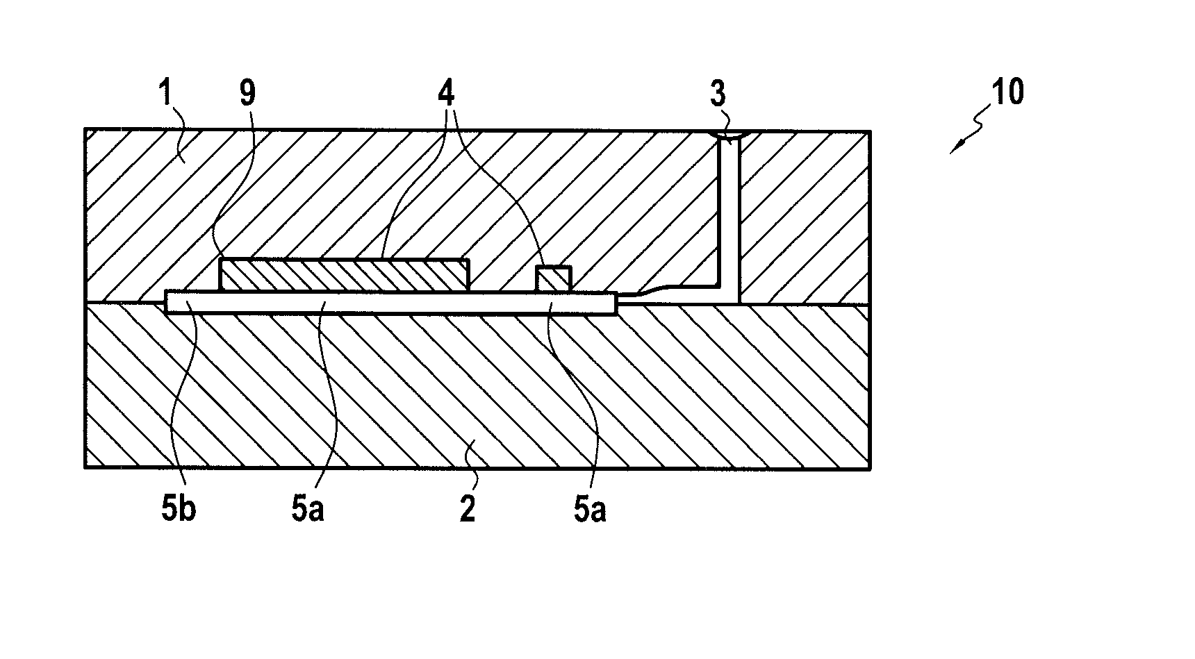
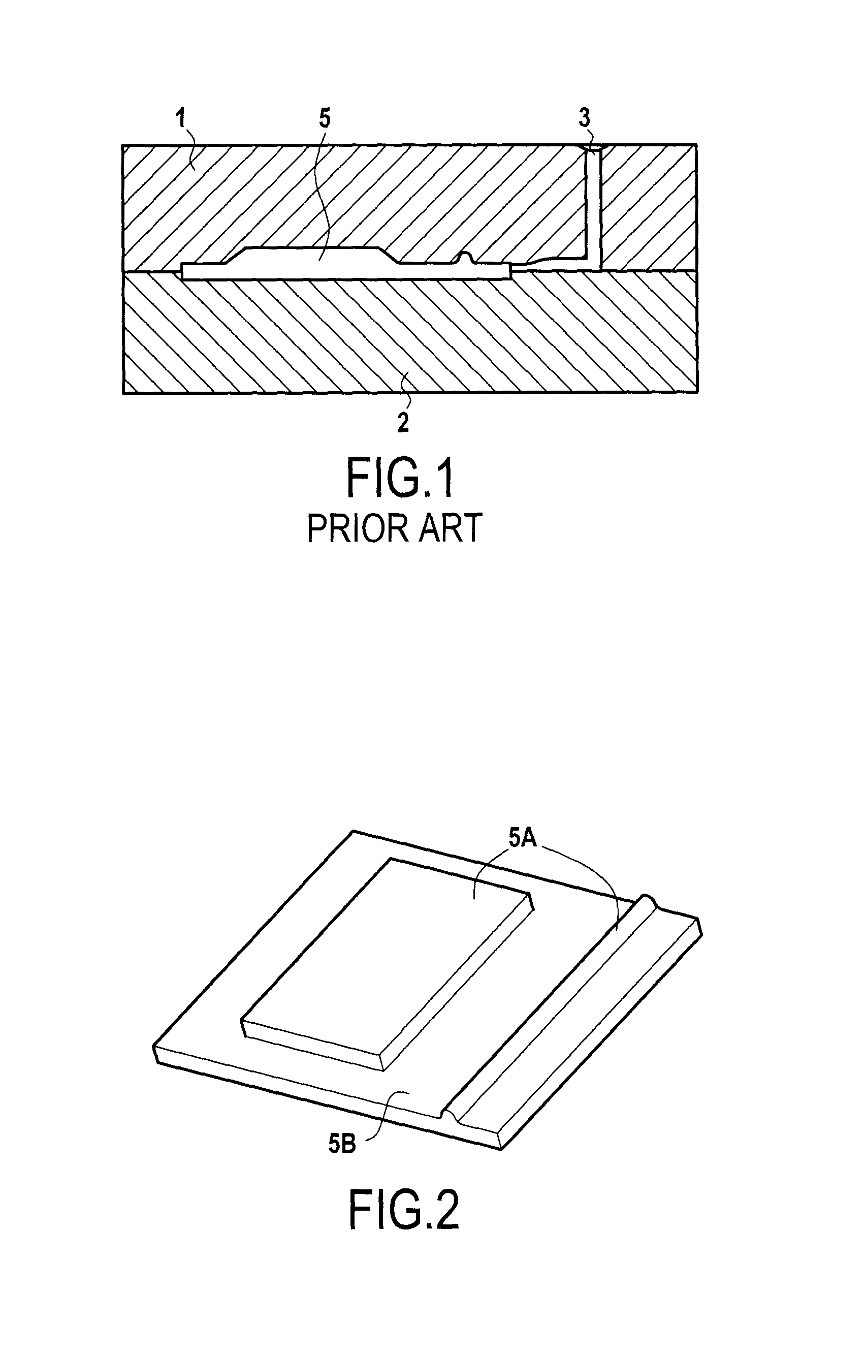
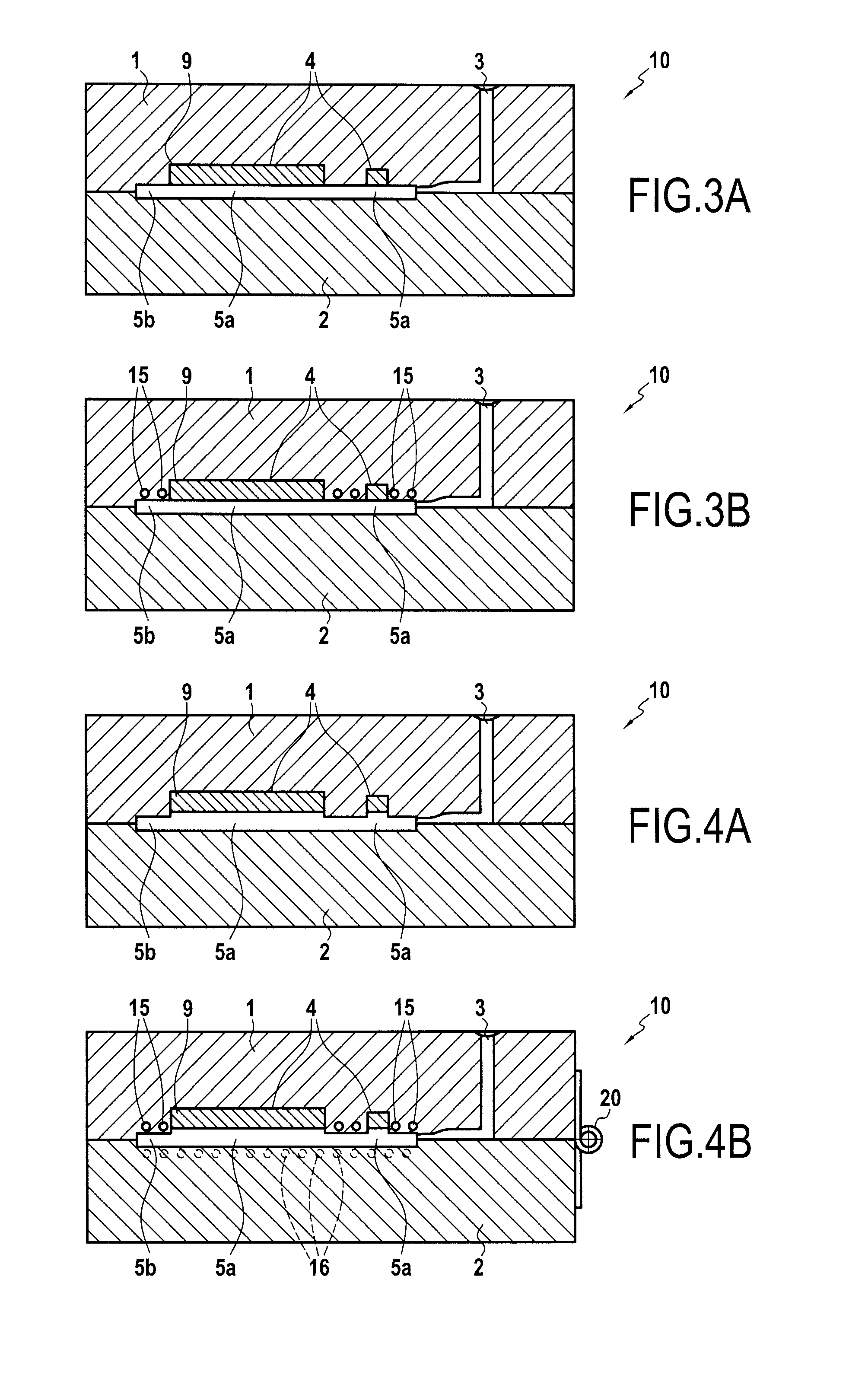
[0048]FIG. 3 illustrates an exemplary mold according to embodiments of the present disclosure, this mold being configured to form a part substantially similar to that shown at FIG. 2, while avoiding drawbacks of other molding systems such as that shown at FIG. 1. As shown in FIG. 3, such a mold includes at least one injection nozzle 3, a first part 1, and a second part 2, where the first and second parts 1 and 2 are configured to be joined together to form mold cavity 5 between them.

[0049]First and second parts 1 and 2 may be formed from any suitable material capable of withstanding temperatures associated with injection molding. For example, first and second parts 1 and 2 may be formed from aluminum and alloys thereof...


PUM

PropertyMeasurementUnit
Fractionaaaaaaaaaa
Temperatureaaaaaaaaaa
Timeaaaaaaaaaa

Abstract

A mold for molding an object having a section of increased thickness includes a mold cavity including a first zone and a second zone and a means for providing a different thermal conductivity at the first and second zone of the mold cavity.

Description

FIELD OF THE DISCLOSURE[0001]The present disclosure is related to the molding of objects, and more particularly to injection molding plastic objects having one or more sections of increased thickness.BACKGROUND OF THE DISCLOSURE[0002]Molding of various plastic parts has been performed by various methods in the past. Such molding typically involves a mold into which molten plastic material is provided and solidified to take the form of a cavity within the mold. Once solidified, the mold may be opened and the object having the shape of the cavity may then be removed.[0003]FIG. 1 is an exemplary mold according to currently available systems used for molding plastic parts. As shown, such a mold typically includes two parts 1 and 2 that when joined form a mold cavity 5 between them. An injection nozzle 3 of the mold enables the introduction of molten plastic material into mold cavity 5. The mold cavity 5 provides areas enabling more or less material to accumulate in such areas, thereby c...

Claims


Application Information

Patent Timeline
IPC IPC(8): B29C45/73B29C45/26B29C44/02B29C33/02B29C33/38
CPCB29C45/73B29C33/02B29L2031/3005B29C44/02B29C45/26B29C33/38B29C33/3828B29C44/027B29C44/0407B29C44/58B29C45/762B29C2045/7343
Inventor KAMEYAMA, TSUYOSHIPRINCE, MICHAEL
Owner TOYOTA MOTOR EUROPE
Why Eureka
Eureka Blog
Learn More