
Transport Vehicle, and Transport Vehicle Air Cleaner

a technology for transport vehicles and air cleaners, which is applied in the direction of machines/engines, auxillary pretreatment, and separation processes, etc., can solve the problems of reducing insulation resistance, reducing insulation resistance, and affecting the performance of the generator

Active Publication Date: 2015-11-12
NIHON KENKI CO LTD
View PDF3 Cites 6 Cited by
  • Summary
  • Abstract
  • Description
  • Claims
  • Application Information

AI Technical Summary

Benefits of technology

The present invention is a haulage vehicle with a cooling air supply assembly mounted thereon that includes an air cleaner. The air cleaner is realistic in terms of fabrication steps and cost aspect. The invention also provides an air cleaner that is realistic and suitable for being mounted on a haulage vehicle. The technical effect of the invention is to provide a cooling air supply assembly with an air cleaner that is practical and affordable.

Problems solved by technology

As the generator produces heat as an energy loss due to the electric resistances of its parts and coils, there is a need to forcedly supply cooling air into the generator to perform cooling of the generator.
If dust-containing air is directly taken into a generator, a potential problem may therefore arise in that insulating coatings in the generator may be worn out by dust and the insulation resistance may be lowered.
If the use of the generator is continued with its insulating coatings having been worn out, a potential problem may arise in that the wearing may proceed to complete loss of the insulating coatings, coils may eventually undergo dielectric breakdown, and a rotor may become no longer usable.
However, a dust collector equipped with a filter requires scheduled maintenance, and moreover is accompanied by a concern about a possible reduction in cooling performance through the clogging of the filter.

Method used


Image

  • Transport Vehicle, and Transport Vehicle Air Cleaner
  • Transport Vehicle, and Transport Vehicle Air Cleaner
  • Transport Vehicle, and Transport Vehicle Air Cleaner

Examples


Embodiment Construction

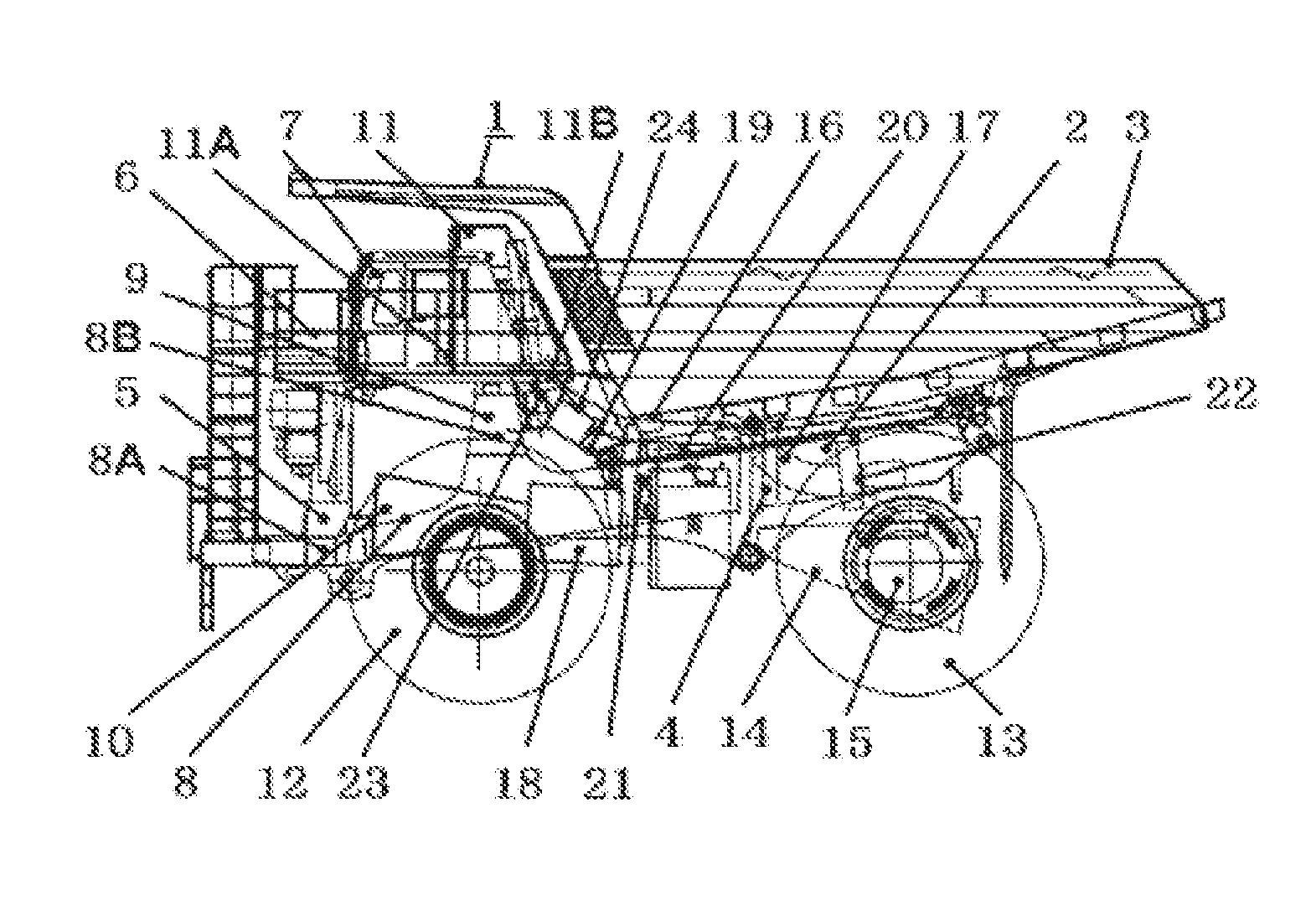
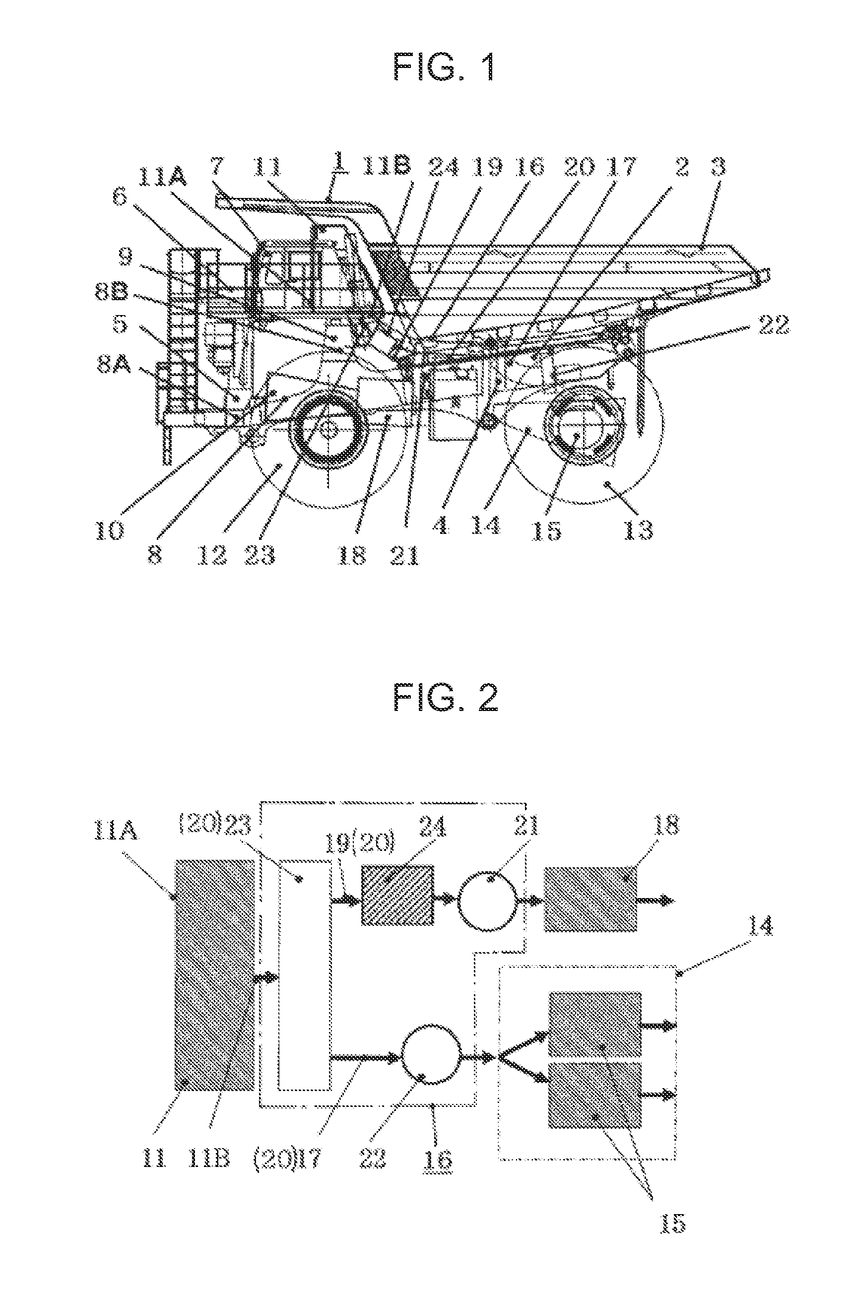
[0021]Taking, as an example, a dump truck for hauling crushed stones (minerals) excavated at a mine or the like, a haulage vehicle according to an embodiment of the present invention will hereinafter be described with reference to the drawings.

[0022]In FIG. 1, numeral 1 designates a dump truck as a large-sized haulage vehicle, and the dump truck 1 is substantially configured of a vehicle body 2 in the form of a solid frame structure, and a load body (vessel) 3 mounted on the vehicle body 2 to load therein a large amount of heavy materials to be hauled, such as, crushed stones. On the other hand, the vehicle body 2 is configured including a frame 4, a housing 5, a deck 6 and a cab 7, and the like. These frame 4, housing 5, deck 6 and cab 7 will be described subsequently herein.

[0023]The frame 4 serves as a base for the vehicle body 2, and is formed as a rigid support structure body having a plate working structure. The frame 4 is substantially configured by a base frame 8 extending i...


PUM

PropertyMeasurementUnit
Diameteraaaaaaaaaa

Abstract

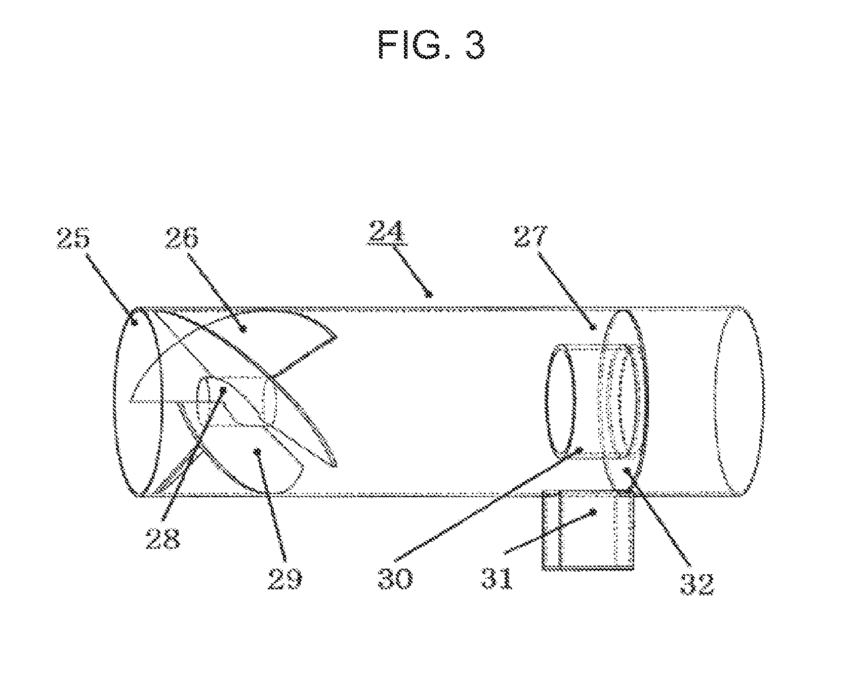
Provided is a haulage vehicle having an air cleaner that is realistic from the viewpoints of fabrication steps and cost aspect. An air cleaner (24) arranged in a haulage vehicle is provided with a swirling flow generator (26), a separator (27) and an outer cylindrical casing (25). The swirling flow generator has a fixed shaft (28) and a plurality of guide blades (29) arranged and shifted from one another over a predetermined angle in a direction in which the guide blades rotate about the fixed shaft, and by the plurality of guide blades, a swirling flow of cooling air is generated. The separator has a flange (32) attached on and along an inner peripheral wall of the outer cylindrical casing (25), an inner cylindrical member (30) arranged on an outer edge of a center bore of the flange, and a collection pocket (31). Dust contained in the cooling air is taken by the swirling flow into a space between the inner cylindrical member and the outer cylindrical casing and is allowed to accumulate in the collection pocket.

Description

TECHNICAL FIELD[0001]This invention relates to a haulage vehicle such as a dump truck that hauls, for example, minerals and the like excavated at a mine or the like, and also to an air cleaner suitable for the haulage vehicle.BACKGROUND ART[0002]At an excavation site, a mine or the like for open-pit mining, work is generally performed including excavating a large amount of minerals and earth or sand by hydraulic excavators and loading a large amount of excavated minerals (crushed stones) and the like on large-sized haulage vehicles called “dump trucks” to haul them to an unloading site such as a port.[0003]A large-sized dump truck that adopts an AC drive traction system drives a generator by an engine, and subsequent to control of the resulting electricity by an inverter, drives AC motors to perform traveling. As the generator produces heat as an energy loss due to the electric resistances of its parts and coils, there is a need to forcedly supply cooling air into the generator to p...

Claims


Application Information

Patent Timeline
IPC IPC(8): B60K11/06F01P11/12B60K6/46B60P1/04B60K7/00
CPCB60K11/06B60P1/04Y10S903/902B60K6/46F01P11/12B60K7/0007B60Y2200/142B60K2001/006B60Y2200/92Y02T10/62H02K9/04
Inventor OUE, TSUYOSHIODA, NAOKAZU
Owner NIHON KENKI CO LTD
Learn More