
Hydraulic Block for a Hydraulic Assembly of a Slip-Regulated, Hydraulic Vehicle Brake System, and a Hydraulic Vehicle Brake System

a technology of hydraulic assembly and hydraulic block, which is applied in the direction of braking system, functional valve type, operating means/releasing devices of valves, etc., can solve problems such as adversely affecting measurement, and achieve the effect of reducing the number of pressure sensors and improving slip regulation

Active Publication Date: 2015-11-12
ROBERT BOSCH GMBH
View PDF12 Cites 7 Cited by
  • Summary
  • Abstract
  • Description
  • Claims
  • Application Information

AI Technical Summary

Benefits of technology

The invention is about arranging the receiver for the brake master cylinder pressure sensor and the receivers for pressure sensors in the hydraulic block of a vehicle brake system in a space-saving and compact way. This helps to save space and reduces the length of the connection lines, which can improve the measurement result and slip regulation. The hydraulic block should also be suitable for predrilling. The use of short and less angled connection lines for pressure sensors reduces the impact of fluctuating brake pressure and improves the measurement result. Overall, this invention helps to optimize the performance of the vehicle brake system.

Problems solved by technology

Long and angled lines choke the pressure changes and can create pressure reflections, adversely affecting the measurement result.

Method used


Image

  • Hydraulic Block for a Hydraulic Assembly of a Slip-Regulated, Hydraulic Vehicle Brake System, and a Hydraulic Vehicle Brake System
  • Hydraulic Block for a Hydraulic Assembly of a Slip-Regulated, Hydraulic Vehicle Brake System, and a Hydraulic Vehicle Brake System
  • Hydraulic Block for a Hydraulic Assembly of a Slip-Regulated, Hydraulic Vehicle Brake System, and a Hydraulic Vehicle Brake System

Examples


Embodiment Construction

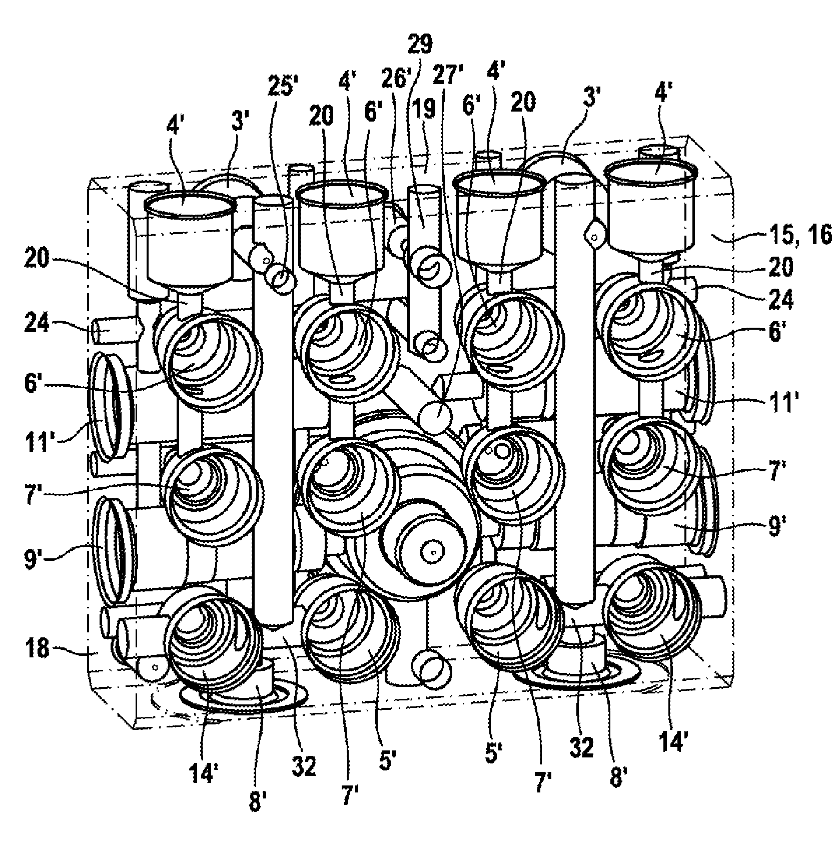
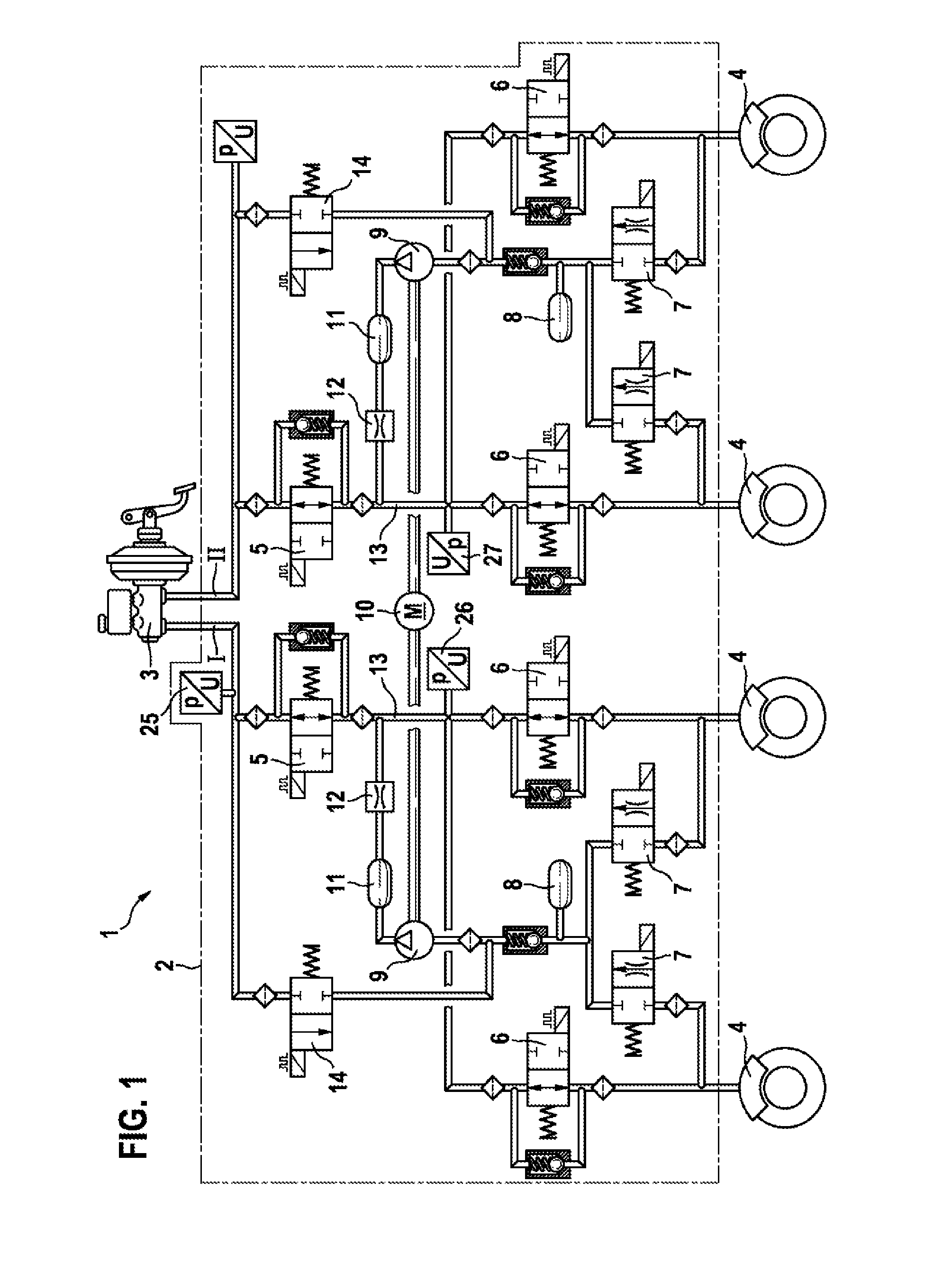
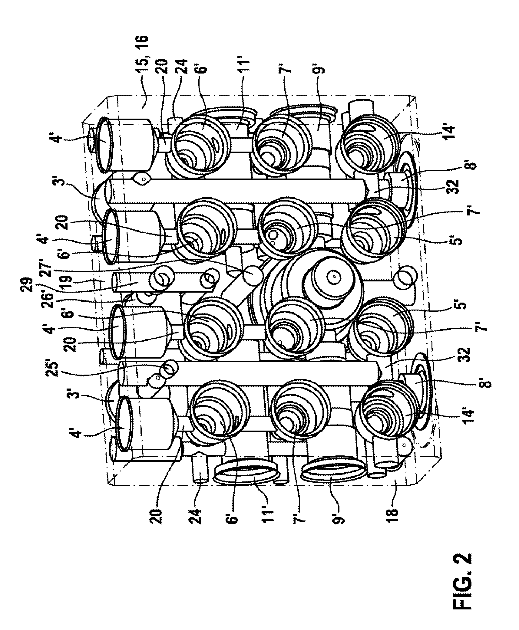
[0015]The slip-regulated, hydraulic, dual circuit vehicle brake system 1 shown in FIG. 1 comprises a hydraulic assembly 2, a dual circuit brake master cylinder 3 to which the hydraulic assembly 2 is connected, and wheel brakes 4 which are connected to the hydraulic assembly 2. The hydraulic assembly 2 comprises the hydraulic components, listed in the paragraph below, of a slip control system of the vehicle brake system 1.

[0016]Each brake circuit I, II of the vehicle brake system 1 is connected to the brake master cylinder 3 via a shut-off valve 5. The wheel brakes 4 are connected to the shut-off valves 5 via brake pressure build-up valves 6. In each brake circuit I, II, a hydraulic accumulator 8 and a suction side of a hydraulic pump 9 are connected to the wheel brakes 4 via brake pressure reduction valves 7. The two hydraulic pumps 9, often also designated return pumps, are jointly driven by an electric motor 10. Damper chambers 11 are connected on the pressure sides of the hydraul...


PUM


Abstract

A hydraulic block for a hydraulic assembly of a slip-regulated, hydraulic vehicle brake system, comprises a first plurality of receivers aligned in a first row that are each configured to fluidly connect to a respective brake pressure, and a second plurality of receivers aligned in a parallel second row that are each configured to fluidly connect to a respective brake pressure reduction valve. The second row is spaced from the first row in a first direction. The hydraulic block further comprises a first further receiver that fluidly connects to a brake master cylinder pressure sensor. The first further receiver is located perpendicularly offset from the first row in a second direction opposite the first direction and within a plane extending between two of the first plurality of receivers and between two of the second plurality of receivers and that is outside of a center plane defined by the hydraulic block.

Description

[0001]The invention concerns a hydraulic block for a hydraulic assembly of a slip-regulated hydraulic vehicle brake system, with the features of the preamble of claim 1. In detail, the invention concerns a drilling of such a hydraulic block, i.e. details of an arrangement of hydraulic components of a slip control system on and in the hydraulic block, and their hydraulic connections in the hydraulic block. The invention also concerns a hydraulic vehicle brake system with the features of the preamble of claim 10.PRIOR ART[0002]Such hydraulic blocks are known. They are typically squat, cuboid metallic blocks for installation of hydraulic components such as hydraulic pumps, magnetic valves, hydraulic accumulators and damper chambers of a slip-regulated vehicle brake system. The hydraulic blocks hold the hydraulic components mechanically and connect them hydraulically through typically drilled connecting lines. A hydraulic block fitted with the hydraulic components forms a hydraulic asse...

Claims


Application Information

Patent Timeline
IPC IPC(8): B60T8/36B60T8/48
CPCB60T8/368Y10T137/1842B60T8/4872
Inventor SCHLITZKUS, MICHAELTANDLER, JUERGENMAYR, MATTHIASWEH, ANDREAS
Owner ROBERT BOSCH GMBH
Learn More