System, method and apparatus for combined ball segment valve and check valve

a combined ball segment and valve body technology, applied in the field of valves, can solve the problems of insufficient supply of relatively low sealing force, insufficient and generally ineffective arrangement of check valves to serve in double block and bleed arrangement, etc., and achieve the effect of saving space, cost and weigh

Active Publication Date: 2015-11-12
SAUDI ARABIAN OIL CO
View PDF0 Cites 7 Cited by
  • Summary
  • Abstract
  • Description
  • Claims
  • Application Information

AI Technical Summary

Benefits of technology

[0007]Described herein are apparatuses, systems and methods for controlling a flow of fluid through a fluid system. A valve apparatus is provided within a fluid system for handling a flammable working fluid. The valve apparatus includes a spring-assisted, dual plate check valve and a ball segment valve arranged such that a flapper door of the check valve longitudinally overlaps a ball segment of the ball segment valve when each are in respective open positions. Thus, the valve apparatus maintains a face-to-face dimension of a standard ball valve, and thus enables positive isolation and directional fluid control in a congested fluid system. The valve apparatus offers space, cost and weight savings over single valves.

Problems solved by technology

One application where this arrangement is generally ineffective is in positive energy isolation.
Although a ball valve by itself may, in some instances, be used to establish the two positive seals for a double block and bleed arrangement, e.g., one seal at each of the two annular valve seats, a check valve is generally ineffective to serve in a double block and bleed arrangement.
In some applications, this relatively low sealing force is insufficient to provide a safe working environment for welding or other maintenance activities on downstream fluid components.

Method used


Image

  • System, method and apparatus for combined ball segment valve and check valve
  • System, method and apparatus for combined ball segment valve and check valve
  • System, method and apparatus for combined ball segment valve and check valve

Examples


Embodiment Construction

[0026]The present invention will now be described more fully hereinafter with reference to the accompanying drawings which illustrate embodiments of the invention. This invention may, however, be embodied in many different forms and should not be construed as limited to the illustrated embodiments set forth herein. Rather, these embodiments are provided so that this disclosure will be thorough and complete, and will fully convey the scope of the invention to those skilled in the art.

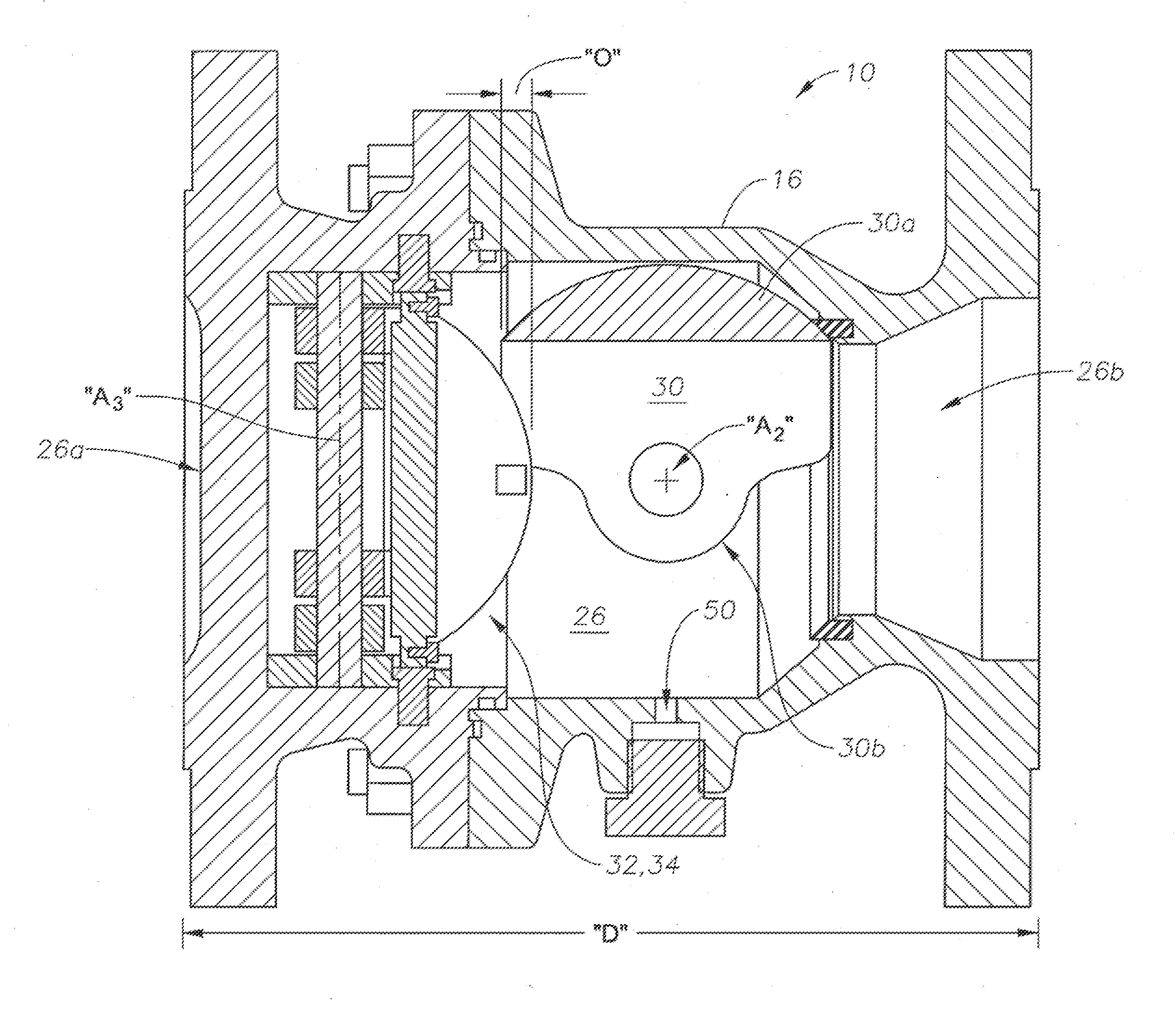
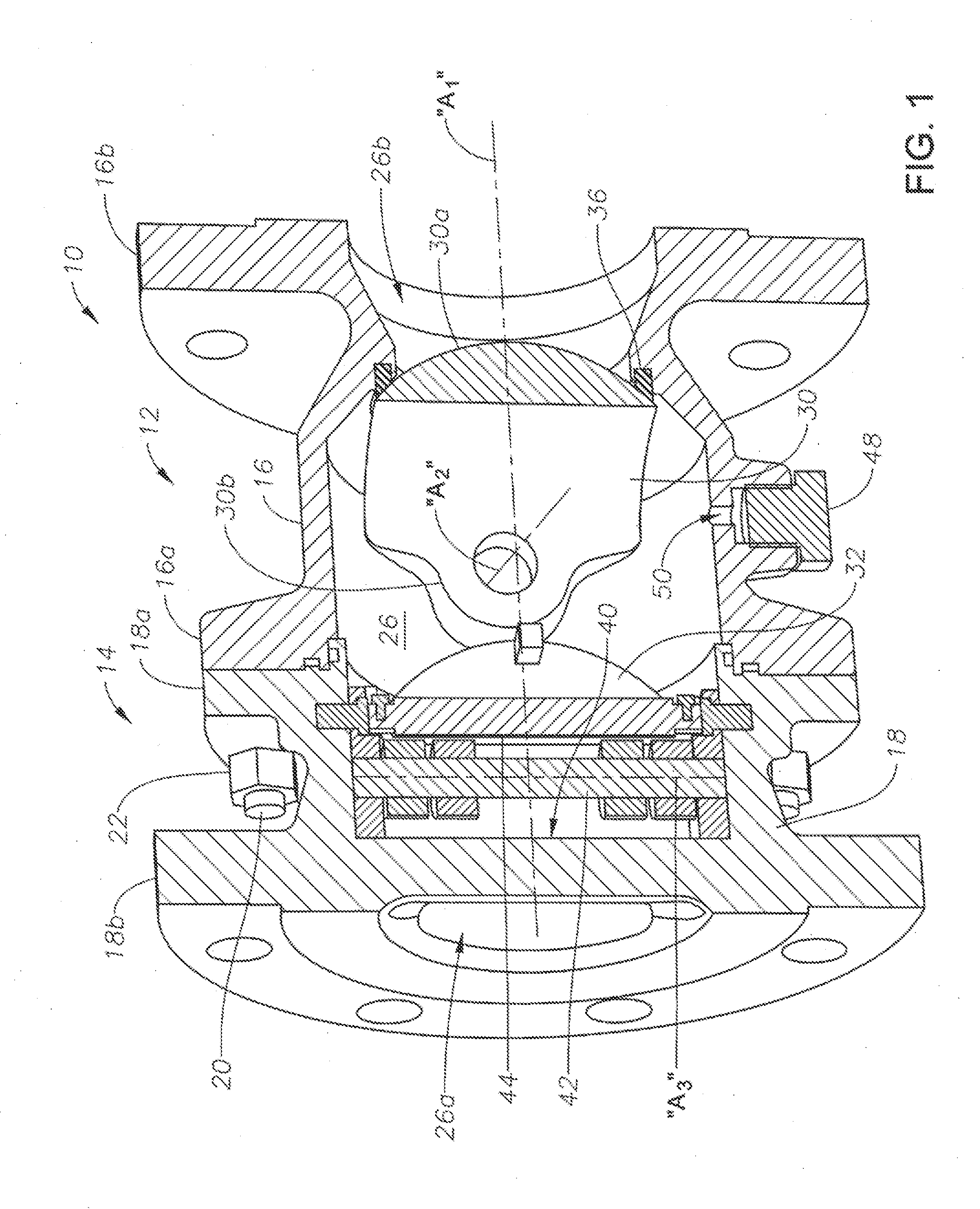
[0027]Referring to FIG. 1, valve apparatus 10 is constructed in accordance with an example embodiment of the present invention. Valve apparatus 10 generally includes a ball segment valve 12 and a check valve 14 coupled thereto. Ball segment valve housing 16 and check valve housing 18 can be formed or cast from any suitable material such as brass, iron or steel, and include respective interfacing inner radial flanges 16a, 18a. Fasteners such as bolts 20 and nuts 22 couple inner radial flanges 16a, 18a tog...


PUM


Abstract

A valve apparatus including a check valve and a ball segment valve is provided within a fluid system for handling a flammable working fluid. The valve apparatus is arranged such that flapper doors of the check valve longitudinally overlaps a ball segment of the ball segment valve when each are in respective open positions such that the valve apparatus maintains a face-to-face dimension of a standard ball valve. The valve apparatus can thus provide positive isolation and directional fluid control in a congested fluid system with space savings over single valves. An isolated chamber is defined between the flapper doors and the ball segment when each is in a respective closed position. A non-flammable fluid is injected into the isolated chamber to urge the flapper doors and ball segment toward the closed positions to thereby provide a safe environment for performing maintenance operations on downstream fluid components.

Description

BACKGROUND OF THE INVENTION[0001]1. Field of the Invention[0002]Embodiments of the present invention relate generally to valves for controlling flow of a working fluid through a fluid system. In particular, example embodiments of the invention relate to a combination of a ball segment valve and a spring-assisted, dual plate check valve, which together provide redundant or “double-block” sealing to facilitate maintenance of downstream fluid components of the fluid system.[0003]2. Description of the Related Art[0004]In many industrial applications, ball valves and check valves are used to selectively permit and restrict fluid flow through a conduit. Generally, a ball valve includes a curved or spherical member that can be rotated 90 degrees to move the ball valve between open and closed configurations. An opening through the spherical member is aligned with the conduit to open the ball valve, and is rotated out of alignment with the conduit to close the ball valve. The spherical membe...

Claims


Application Information

Patent Timeline
Patent Type & Authority Applications(United States)
IPC IPC(8): F16K15/03F16K15/04
CPCF16K15/033F16K15/04F16K15/181Y10T137/7898F16K15/188Y10T137/87917Y10T137/0324Y10T137/88054F16K27/067F16K15/038F16K15/1848F16K15/1821
Inventor AL-AMRI, OMAR M.
Owner SAUDI ARABIAN OIL CO
Why Eureka
Try Eureka