
Systems and methods for detecting gas leaks

a technology of system and method, applied in the direction of fluid tightness measurement, instruments, structural/machine measurement, etc., can solve the problems of significant safety and environmental impact, leakage, and loss of approximately 1.5% to 8% or more of the total natural gas extracted from the ground, and the known leak detection system and method suffers from a number of drawbacks

Active Publication Date: 2015-11-12
KAIROS AEROSPACE
View PDF25 Cites 46 Cited by
  • Summary
  • Abstract
  • Description
  • Claims
  • Application Information

AI Technical Summary

Benefits of technology

The patent text describes a system, method, and computer-readable media for detecting gas leaks. The system collects light and processes it to generate raw spectral data. The data is then analyzed to identify specific wavelength ranges that are sensitive to different gases. By comparing the data in these ranges to a reference, the system can determine the concentration of the gas leaking. The technical effect of this invention is a more accurate and efficient way to detect gas leaks, which can help to prevent accidents and minimize environmental damage.

Problems solved by technology

The leakage of natural gas from wells, associated equipment, pipelines, distribution networks, and other points leads to a loss of between approximately 1.5% to 8% or more of the total natural gas extracted from the ground.
Additionally, the leakage may have a significant safety and environmental impact.
These known leak detection systems and methods suffer from a number of drawbacks and deficiencies.
First, they are labor intensive and costly.
However, because of this high cost, most sites are currently not inspected on a periodic basis.
Nevertheless, new regulations may require a higher frequency of inspection, which may represent a significant monetary burden in testing.
Second, these systems and methods are subject to variation in a technician's experience and performance, and also to the technician's error.
Third, these solutions are not scalable.
The result is that the cost of monitoring gas leakage via these systems and methods grows rapidly.

Method used


Image

  • Systems and methods for detecting gas leaks
  • Systems and methods for detecting gas leaks
  • Systems and methods for detecting gas leaks

Examples


Embodiment Construction

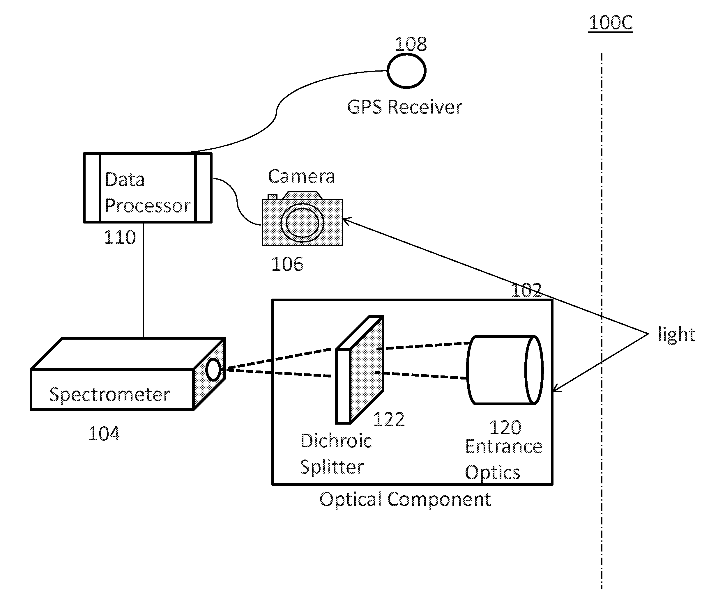
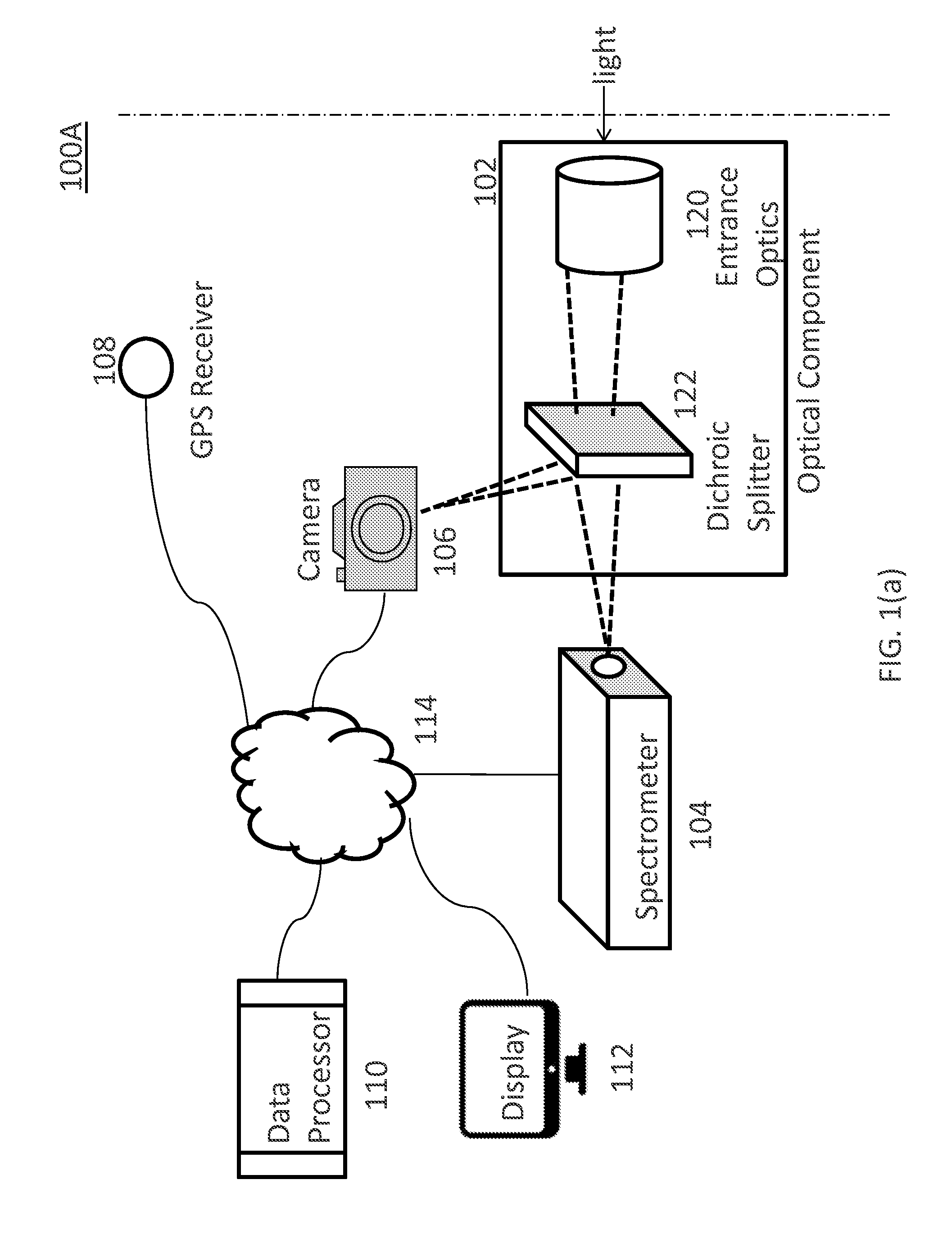
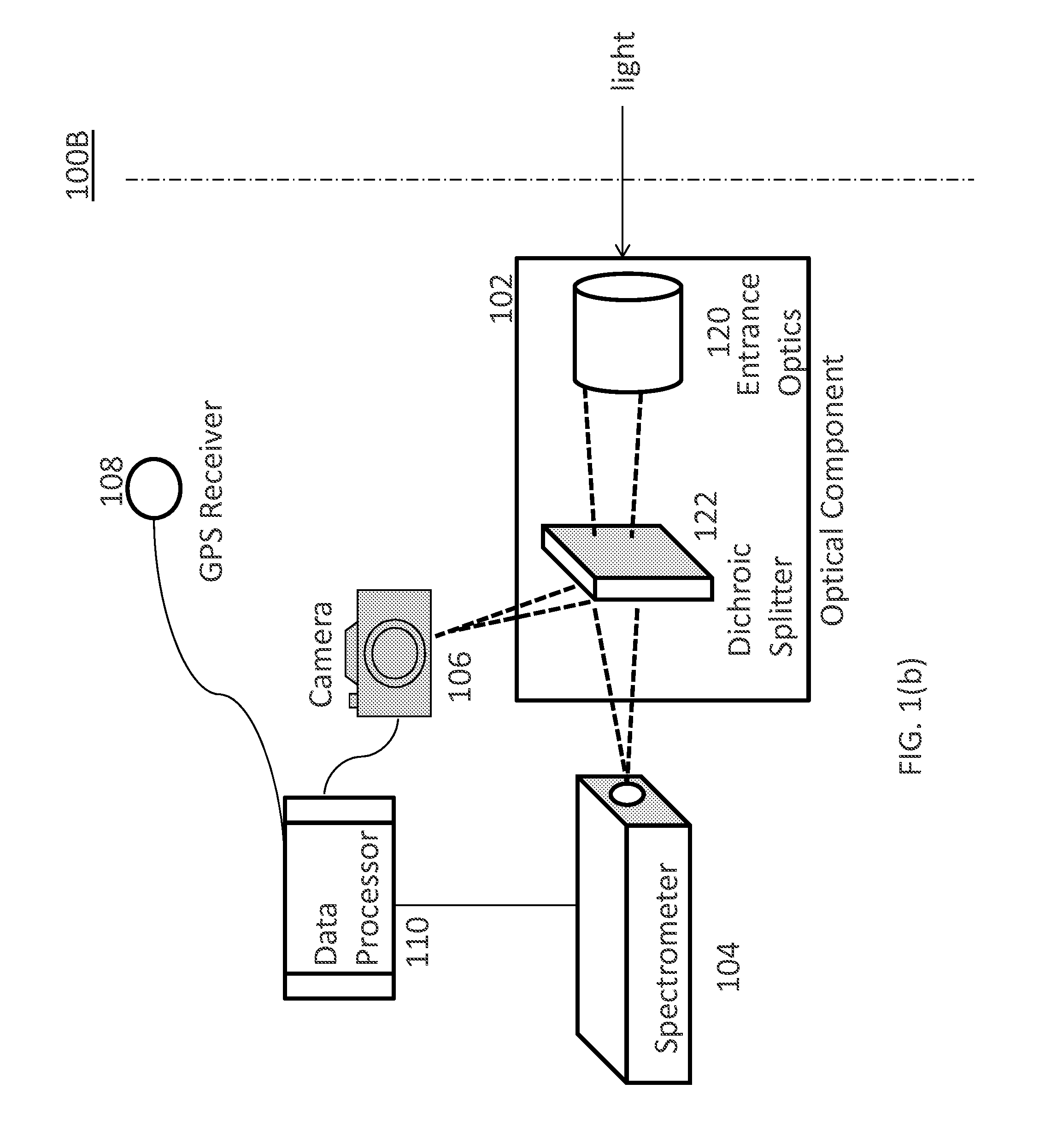
[0030]In the following description, numerous specific details are set forth regarding the systems, methods and media of the disclosed subject matter and the environment in which such systems, methods and media may operate, etc., in order to provide a thorough understanding of the disclosed subject matter. It will be apparent to one skilled in the art, however, that the disclosed subject matter may be practiced without such specific details, and that certain features, which are well known in the art, are not described in detail in order to avoid complication of the disclosed subject matter. In addition, it will be understood that the examples provided below are exemplary, and that it is contemplated that there are other systems, methods and media that are within the scope of the disclosed subject matter.

[0031]The invention is directed to improved systems and methods for detecting gas leaks. More particularly, the invention detects gas leaks or discharges, such as methane or any other...


PUM

PropertyMeasurementUnit
wavelength rangeaaaaaaaaaa
wavelengthaaaaaaaaaa

Abstract

The invention is directed to improved systems, methods, and computer readable media for detecting gas leaks. More particularly, the invention detects gas leaks or discharges, such as methane or any other suitable gases, by analyzing reflected or direct light that passes through a region of enhanced target gas concentration. The invention collects light and processes spectral data of the light. All molecules are subject to rotational motions, vibrational motions, and / or combinations thereof (rovibrational motions), in which the atoms in the molecule are vibrating with respect to each other and / or rotating around each other. When the light passes through the region of the target gas, a portion of the light with certain wavelengths will be absorbed by the target gas due to the rovibrational motions of the target gas molecules. By analyzing the magnitude of absorption at certain wavelengths, one can determine the concentration of certain target gas or gases.

Description

RELATED APPLICATION[0001]This application claims priority to U.S. Provisional Patent Application No. 61 / 991,012, titled “Systems And Methods For Detecting Gas Leaks,” which was filed on May 9, 2014 and is incorporated herein in its entirety.BACKGROUND OF THE INVENTION[0002]1. Technical Field[0003]The invention relates generally to the field of systems and methods for detecting gas leaks.[0004]2. Description of the Related Art[0005]The leakage of natural gas from wells, associated equipment, pipelines, distribution networks, and other points leads to a loss of between approximately 1.5% to 8% or more of the total natural gas extracted from the ground. Additionally, the leakage may have a significant safety and environmental impact. Therefore, there is a need for governments, organizations, and natural gas companies to periodically inspect potential leak sites and detect any leakage.[0006]Traditionally, fugitive emission detection in gas fields is done primarily with forward-looking i...

Claims


Application Information

Patent Timeline
Patent Type & Authority Applications(United States)
IPC IPC(8): G01N21/31G01N21/90
CPCG01N21/90G01N21/3103G01M3/205G01M3/38G01N2021/1795G01N2021/3531G01N21/3504G01N2021/1793
Inventor JONES, BRIAN BUTLERDEIKER, STEVEN WILLIAM
Owner KAIROS AEROSPACE
Learn More