Proximity sensor arrangement

a sensor arrangement and proximity technology, applied in the direction of optical radiation measurement, pulse technique, instruments, etc., can solve the problems of wasting precious battery energy, obstructing the light path, and similar problems, and achieve the effect of improving mechanical stability

Active Publication Date: 2015-11-12
AMS AG
View PDF3 Cites 1 Cited by
  • Summary
  • Abstract
  • Description
  • Claims
  • Application Information

AI Technical Summary

Benefits of technology

[0023]The aperture arrangement can be placed anywhere between the pair comprising the photo-detector and light emitting device on one side, and the cover on the other side, such as residing above the pair of photo-detector and light emitting device. The actual position is restricted by the design constraints discussed above. For example,

Problems solved by technology

A problem, however, can occur when the cell phone is pressed hard against the head of a person who has very dark and dense hair.
When a dark object such as black hair is pressed tightly against the glass, the dark object may obstruct the light path, blocking any reflected IR light from reaching the aperture over the sensor.
In addition to black hair, similar problems can occur when the phone is placed against the side of the head of someone wearing a stocking cap or other object that can occlude any reflected IR light from reaching the detector.
With very dense opaque objects, the problem can also occur with light coloured objects, since they can prevent reflected light passing through the LED aperture, from reaching the sensor aperture, by virtue of being opaque.
The result is that the sensor detects no proximity signal, and electronics in the phone erroneously conclude that there is no nearby proximity target.
In response the cell phone turns the

Method used


Image

  • Proximity sensor arrangement
  • Proximity sensor arrangement
  • Proximity sensor arrangement

Examples


Embodiment Construction

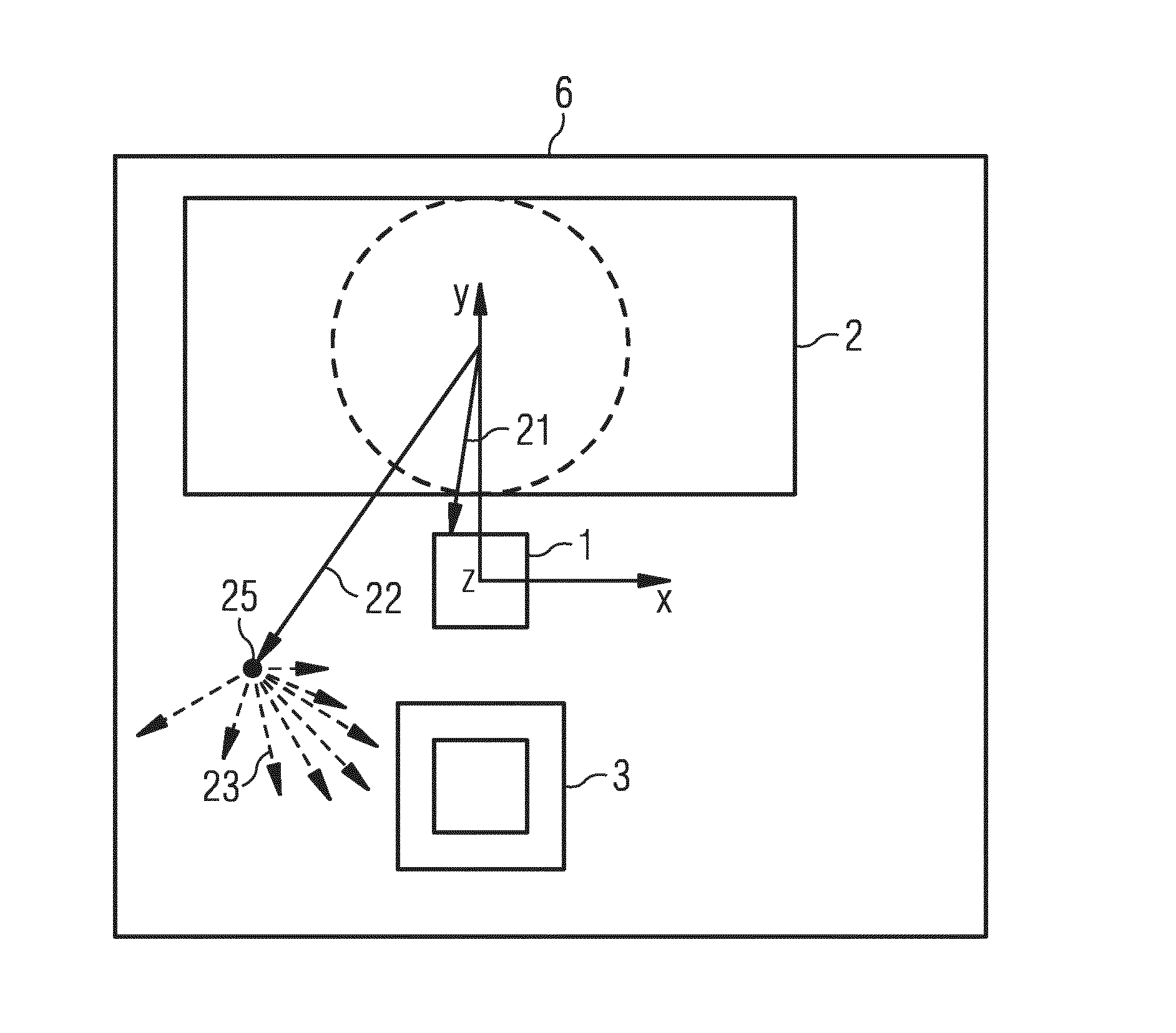
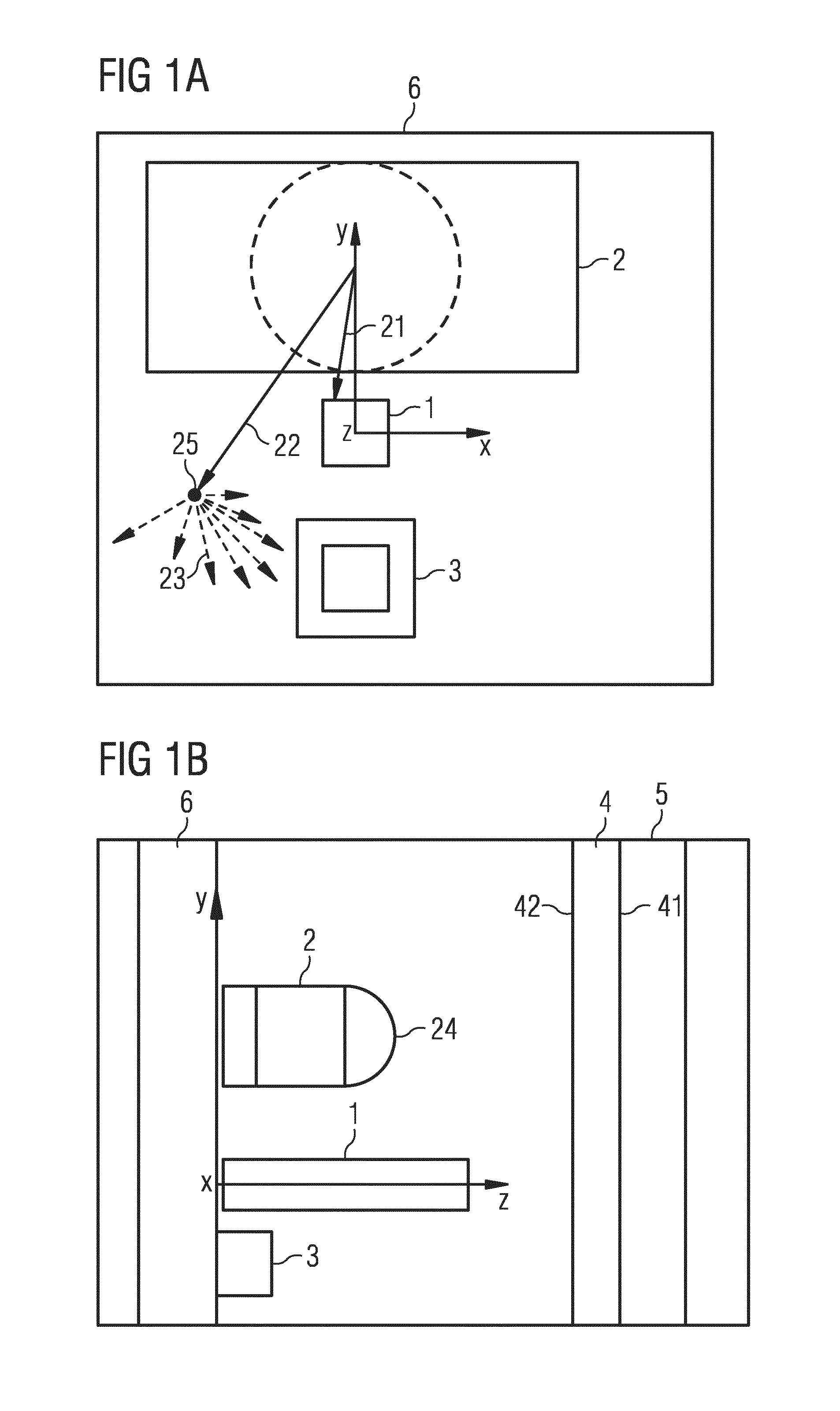
[0035]FIG. 1A shows a top view of an exemplary proximity sensor arrangement according to the principle presented. The sensor arrangement comprises a light emitting device 2, which in particular, is an infrared light emitting diode, and a photo-detector 3 like a charge-coupled device or a photo-diode. These sensor components are mounted on top of a printed circuit board 6 to which they are electrically connected. The printed circuit board 6 defines an x, y plane arranged along principal axes x and y. In particular, the optical barrier 1, the light emitting device 2 and the photo-detector are mounted on the printed circuit board 6 inline with the principal axis y.

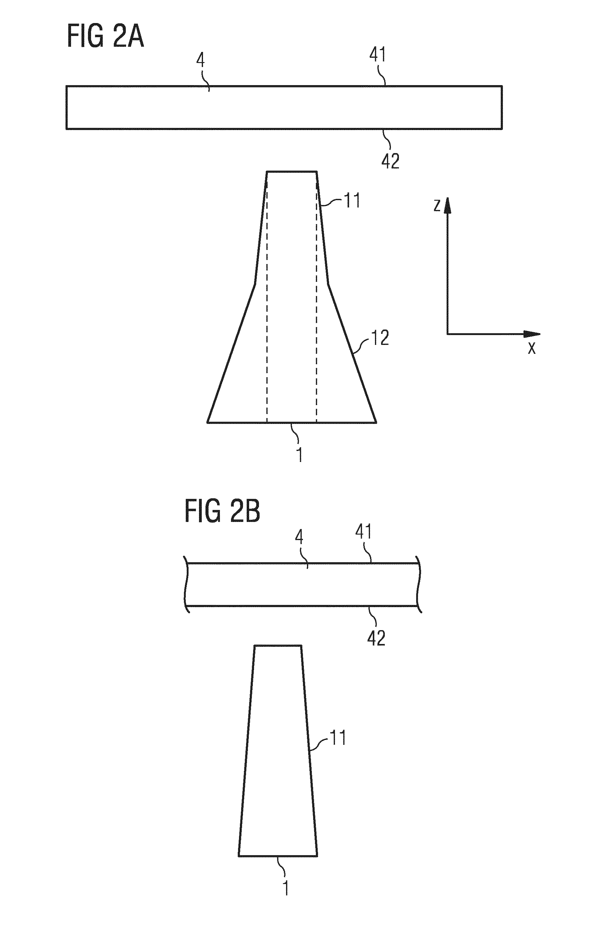
[0036]Placed between the photo-detector 3 and the light-emitting device 2 is an optical barrier 1. The optical barrier 1 comprises a three-dimensional body extending along the principal axes x and y but also along a third principal axis z which is orthogonal with respect to the x, y plane. The optical proximity sensor arrange...


PUM


Abstract

A proximity sensor arrangement comprises an optical barrier being placed between a light emitting device and a photo-detector. The light emitting device, the photo-detector and the optical barrier are covered by a cover. The optical barrier is being designed to block light emitted from the light emitting device to the photo-detector and reflected by the cover by means of specular reflection. Furthermore, the optical barrier is being designed to pass the light emitted from the light emitting device to the photo-detector via the cover and scattered on or above a first surface of the cover facing away from the light emitting device and the photo-detector.

Description

[0001]This application relates to a proximity sensor arrangement.BACKGROUND OF THE INVENTION[0002]Optical proximity sensors are widely used in products such as cell phones and smartphones for detecting proximity to a human head. These sensors often use infra-red (IR) light emitting diodes (LEDs) and optical sensors like photodiodes. The sensor detects the amount of IR light that is reflected from the proximity target, e.g. as the ear area of a human head as a phone is brought into close proximity to the sensor. Proximity detection can be used to trigger response in the phone such as turning off the cell phone screen, in order to conserve cell phone battery power.[0003]A problem, however, can occur when the cell phone is pressed hard against the head of a person who has very dark and dense hair. In such case the hair absorbs most of the incident IR light emitted from the LED, and the small amount of IR light that is reflected eventually has no optical path back to the detector. Altho...

Claims


Application Information

Patent Timeline
IPC IPC(8): G01S7/481G01S17/32G01S17/04
CPCG01S7/4814G01S7/4813G01S17/32G01V8/12H03K17/941H03K2217/94108G01S17/04
Inventor MEHRL, DAVID
Owner AMS AG
Why Eureka
Try Eureka