
Aircraft battery exhaust system

Inactive Publication Date: 2015-11-12
AIRBUS OPERATIONS GMBH
View PDF3 Cites 6 Cited by
  • Summary
  • Abstract
  • Description
  • Claims
  • Application Information

AI Technical Summary

Benefits of technology

The invention is about a way to make a battery system for aircraft that is cheaper and lighter than other designs, and also helps to safely release fluid that might leaks from the battery in case of a failure. The patent also describes how to use this system.

Problems solved by technology

For example, a mechanical failure of an electrolyte container of the first battery may cause a leakage of the battery's electrolyte from the battery in liquid form.
It is, however, also conceivable that certain battery failure conditions such as, for example, a short circuit or an exposure to a high temperature may lead to an evaporation of the battery's electrolyte and thus a release of a high temperature and / or high pressure gas flow from the battery.

Method used


Image

  • Aircraft battery exhaust system
  • Aircraft battery exhaust system
  • Aircraft battery exhaust system

Examples


second embodiment

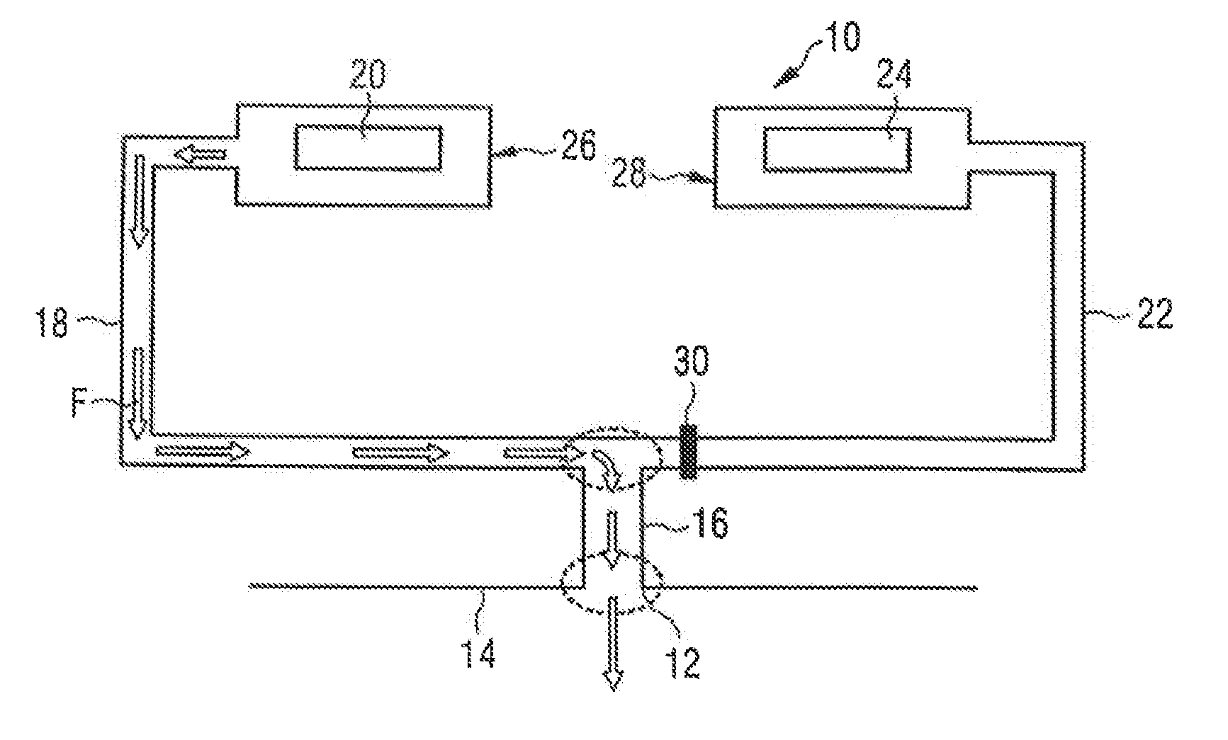
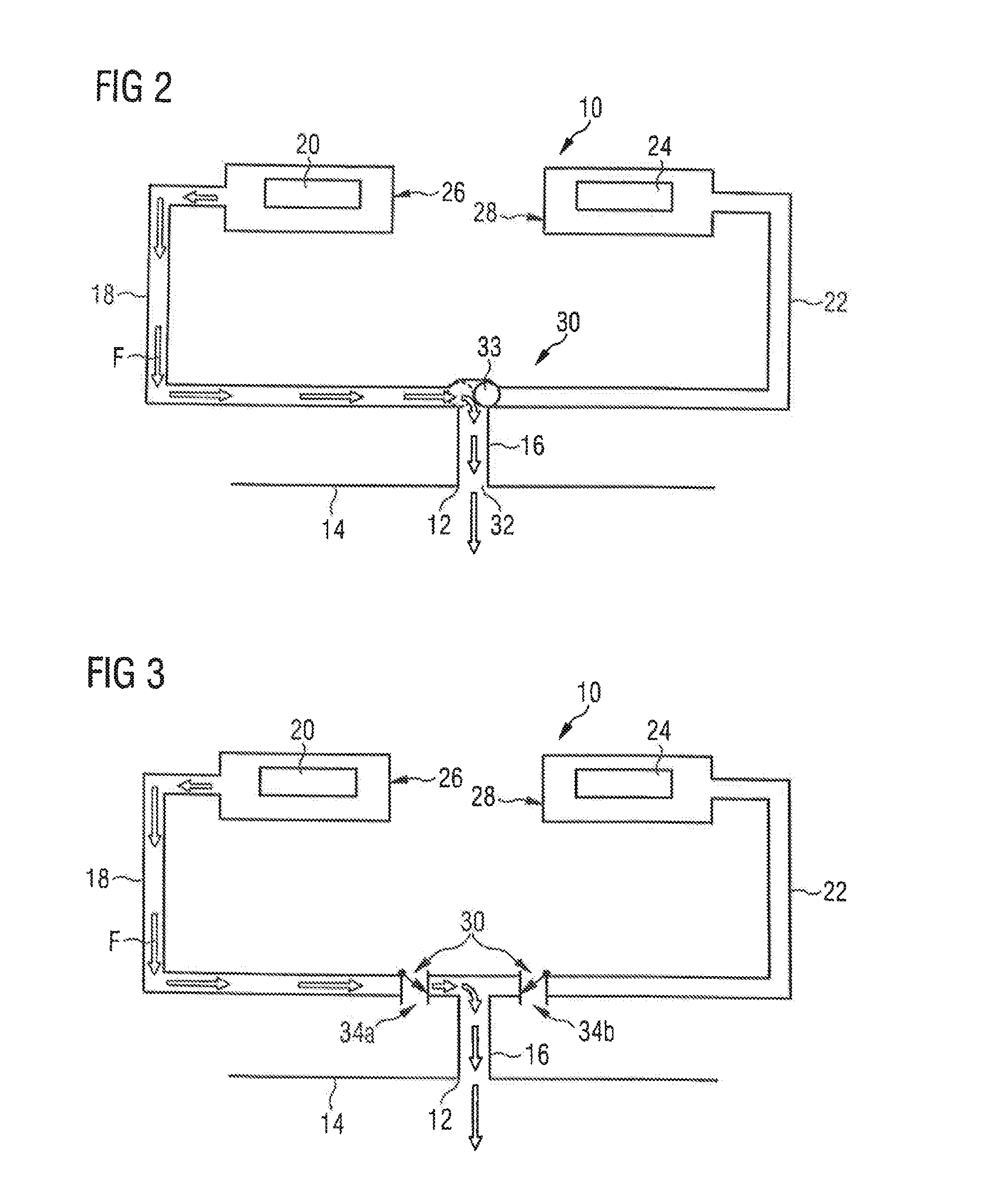
[0036]In an aircraft battery exhaust system 10 shown in FIG. 2, the separation device 30 comprises a multiple non-return valve 33, i.e., a double non-return valve which is disposed at an intersection point of the fluid discharge line 16, the first fluid discharge branch line 18 and the second fluid discharge branch line 22. As shown in FIG. 2, fluid leaking from the first battery 20 reliably is prevented from entering the second fluid discharge branch line 22, but is discharged from the aircraft via the fluid discharge line 16 and the fluid discharge opening 12. In case of a failure of the second battery 24, the double non-return valve 33, in the position indicated in dotted lines in FIG. 2 allows the discharge of fluid leaking from the second battery 24 from the aircraft via the second fluid discharge branch line 22, the fluid discharged line 16 and the fluid discharge opening 12, but prevents the fluid leaking from the second battery 24 from entering the first fluid discharge bran...

third embodiment

[0038]FIG. 3 shows an aircraft battery exhaust system 10 which differs from the arrangement according to FIG. 2 in that the separation device 30 now no longer comprises a double non-return valve, but instead comprises two non-return valves 34a, 34b. One non-return valve 34a, 34b is disposed in each of the first and the second fluid discharge branch line 18, 22. As shown in FIG. 3, in the event of a failure of the first battery 20, a fluid leaking from the first battery 20 exits the aircraft via the first fluid discharge branch line 18, the fluid discharge line 16 and the fluid discharge opening 12, wherein the non-return valve 34b disposed in the second fluid discharge branch line 22 prevents the fluid from entering the second fluid discharge branch line 22. The second battery 24 thus is reliably protected.

[0039]Similarly, in the event of a failure of the second battery 24, fluid leaking from the second battery 24 can be discharged from the aircraft via the second fluid discharge br...


PUM


Abstract

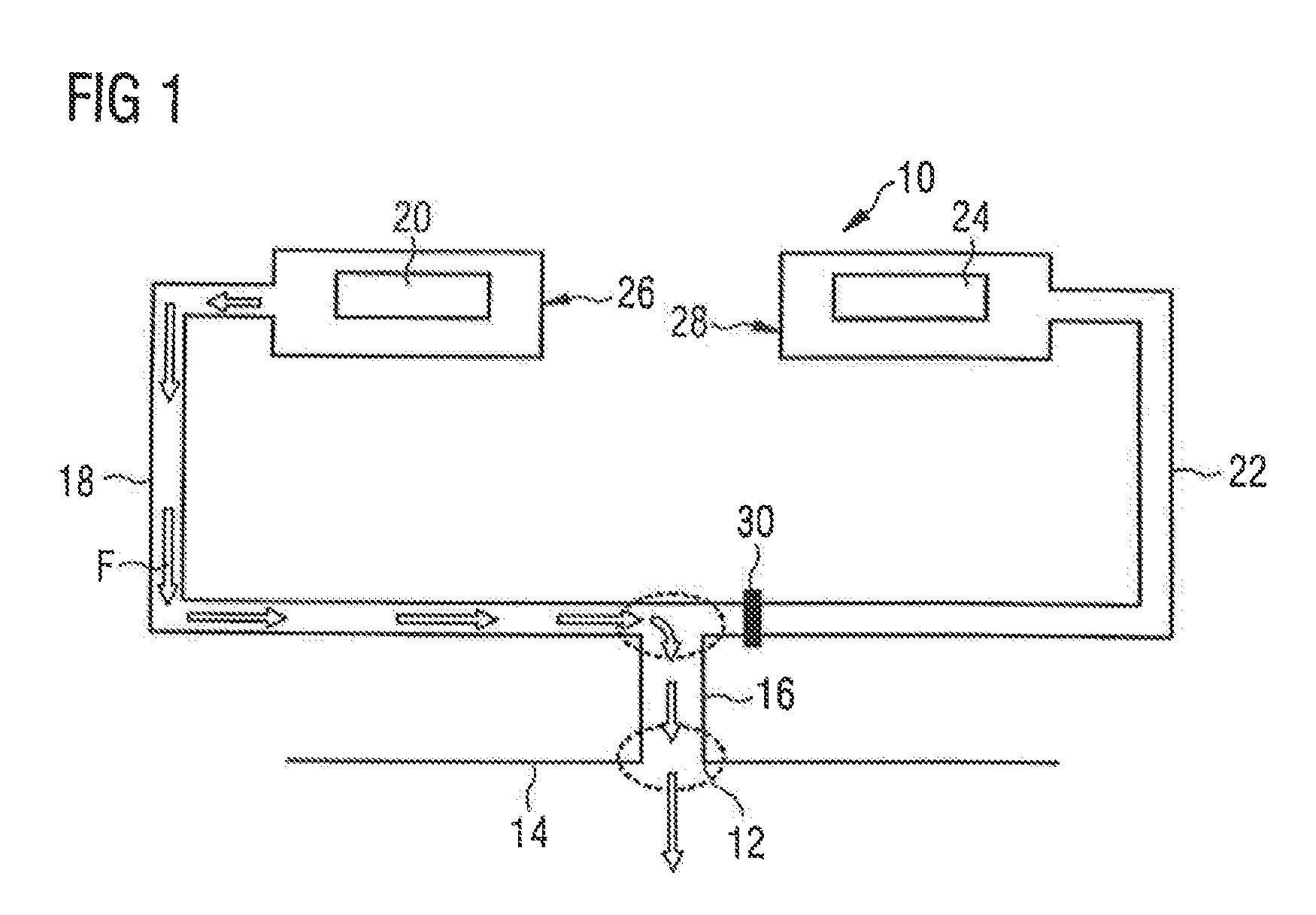
An aircraft battery exhaust system comprises a fluid discharge opening formed in an aircraft outer skin and a fluid discharge line having a first end connected to the fluid discharge opening and a second end. A first fluid discharge branch line has a first end connected to the second end of the fluid discharge line and a second end connected to a first battery in such a manner that a fluid leaking from the first battery is directed into the first fluid discharge branch line. A second fluid discharge branch line has a first end connected to the second end of the fluid discharge line and a second end connected to a second battery in such a manner that a fluid leaking from the second battery is directed into the second fluid discharge branch line.

Description

CROSS-REFERENCES TO RELATED APPLICATIONS[0001]This application claims the benefit of the European patent application No. 14167134.7 filed on May 6, 2014, the entire disclosures of which are incorporated herein by way of reference.BACKGROUND OF THE INVENTION[0002]The invention relates to an exhaust system for venting batteries installed on board an aircraft and to a method of operating an exhaust system of this kind.[0003]As modern passenger aircraft tend to be equipped with more and more electric and electronic devices, an increasing number of batteries, in particular Li-ion batteries, are installed on board the aircraft in order to provide for an appropriate power supply for the electric and electronic devices. The batteries may be used as primary power sources or as backup emergency power sources in case of a failure of the on-board power generators of the aircraft. Certain battery failure conditions such as, for example, a short circuit may lead to an evaporation of electrolytic ...

Claims


Application Information

Patent Timeline
IPC IPC(8): H01M2/12H01M10/052H01M50/358
CPCH01M2/1252H01M2/1241Y10T137/0402H01M2220/20H01M2200/20H01M10/052B64D41/00Y02E60/10H01M50/3425H01M50/358
Inventor DITTMAR, JANZAHNOW, JENSJESSKE, JOHANNESZAMECNIK, JURAJ
Owner AIRBUS OPERATIONS GMBH
Learn More