Support assembly

Inactive Publication Date: 2015-11-19
CHALLENGER HARDWARE
View PDF10 Cites 8 Cited by
  • Summary
  • Abstract
  • Description
  • Claims
  • Application Information

AI Technical Summary

Benefits of technology

[0006]There is therefore a need in the art for providing a mechanism which provides support to an element such as an armrest pad

Problems solved by technology

Either type of water is extremely corrosive to certain materials and may therefore signifi

Method used


Image

  • Support assembly
  • Support assembly
  • Support assembly

Examples


Embodiment Construction

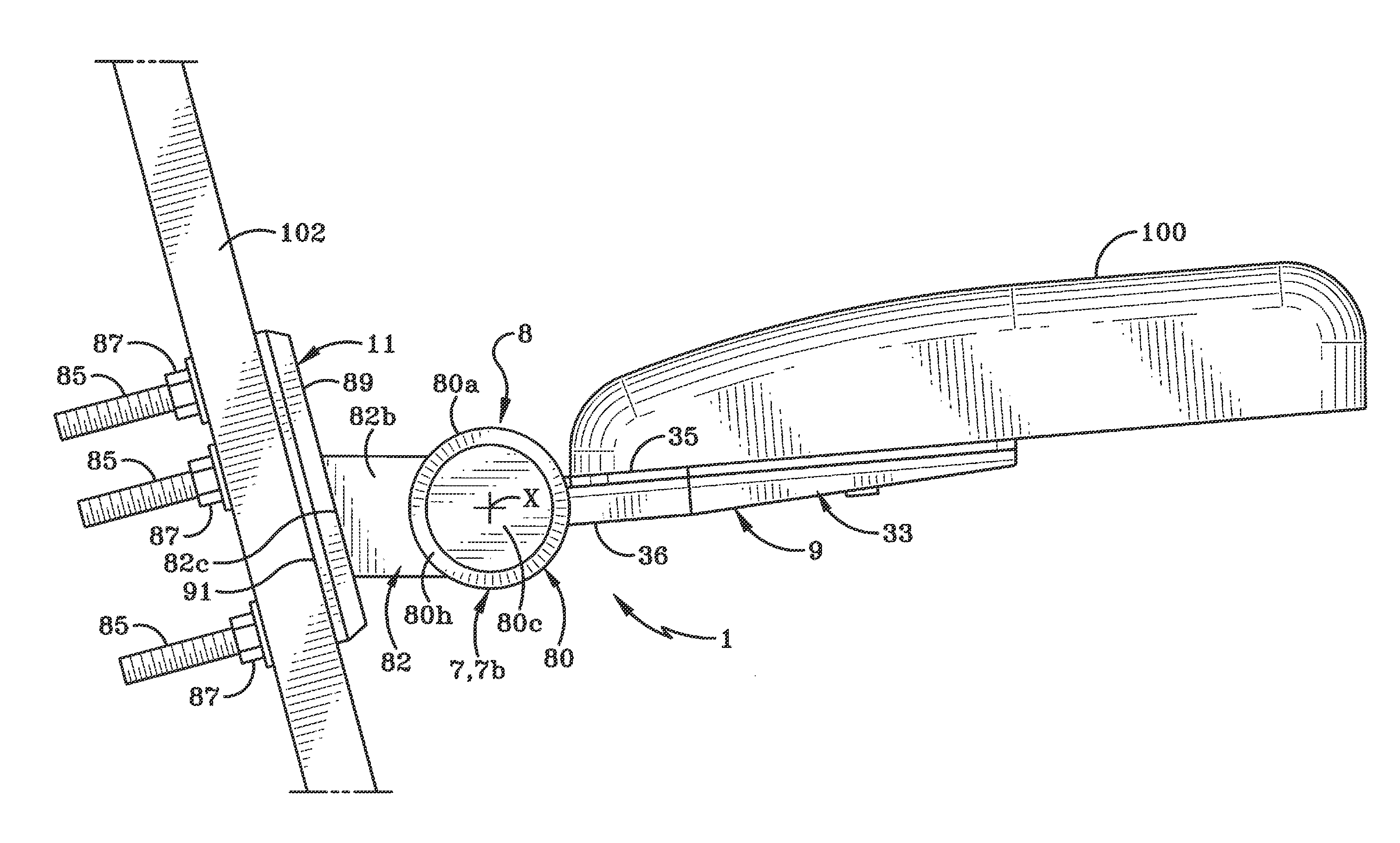
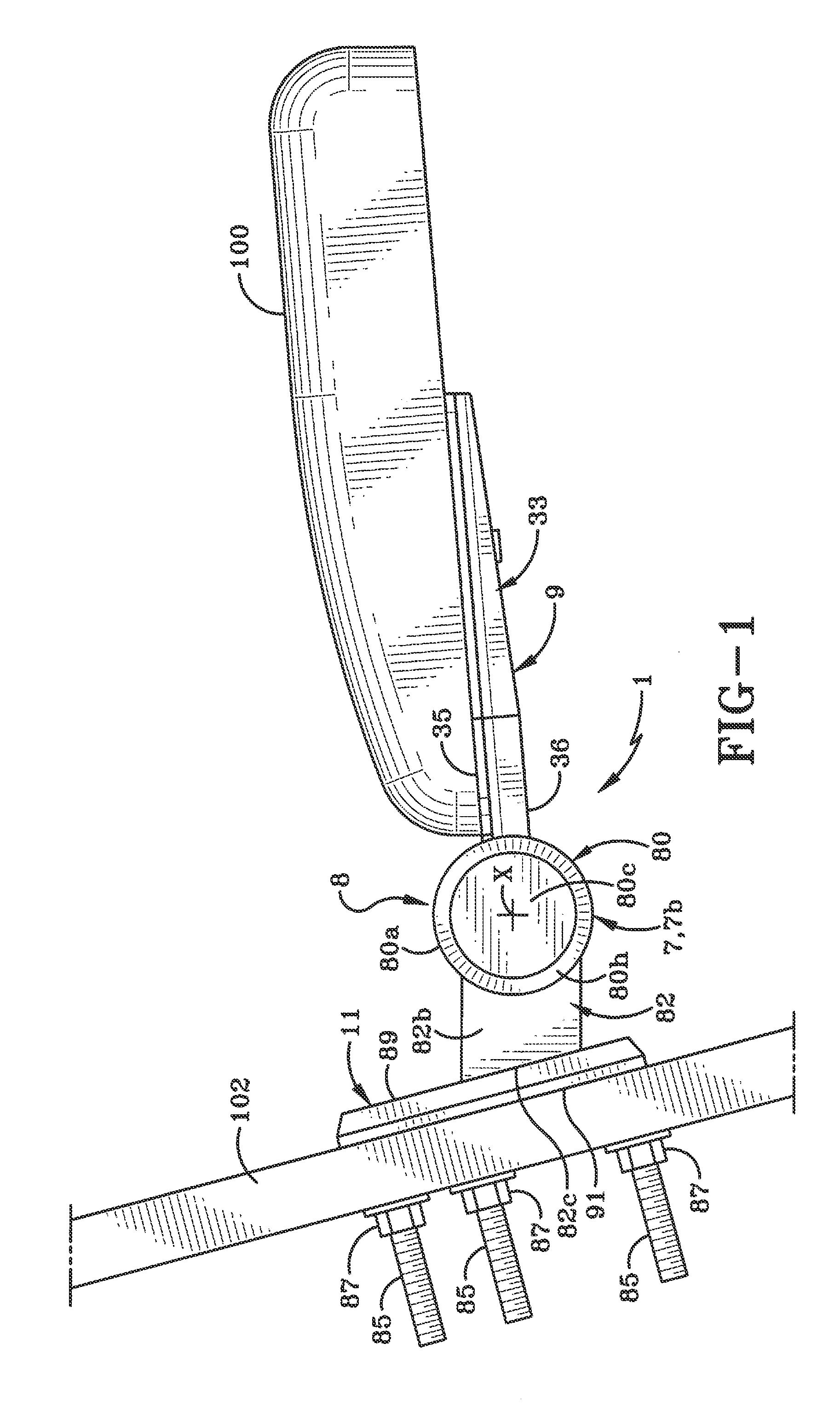
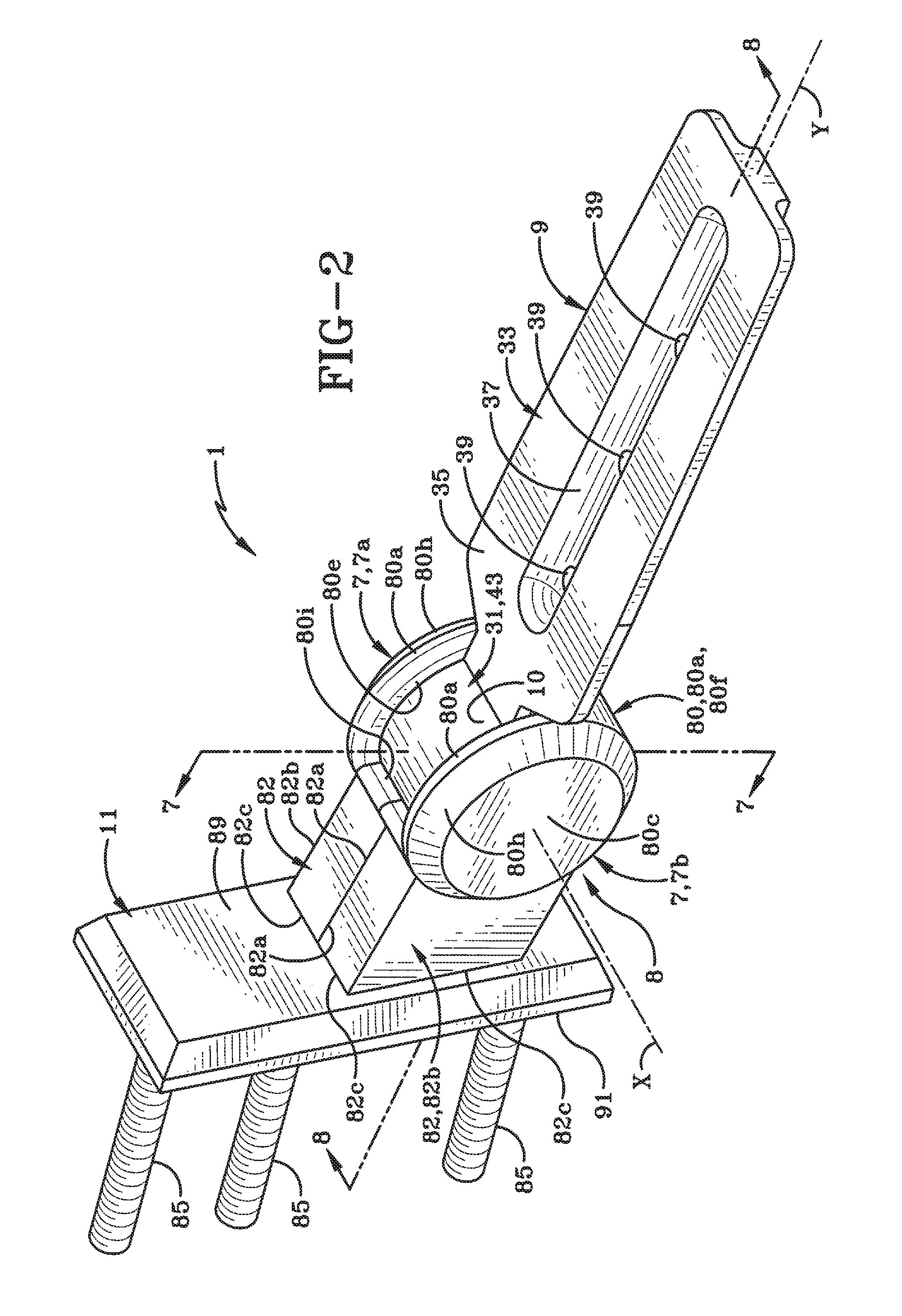
[0023]A support assembly is shown in FIGS. 1-9 and referred to generally herein as support assembly 1. Support assembly 1 may be used to secure an armrest pad 100 to a supporting structure 102, as illustrated in FIG. 1. The combined support assembly 1 and armrest pad 100 may, for instance, be mounted on a supporting structure 102 such as a chair backrest or a vertical or semi-vertical wall on watercraft, aircraft or a land vehicle.

[0024]FIG. 1 shows a first part of support assembly 1 and therefore armrest pad 100 in a first position relative to supporting structure 102. In this first position, armrest pad 100 is in a generally horizontal orientation and may be used to support a person's forearm thereon. FIG. 9, on the other hand, shows the first part of support assembly 1 and therefore armrest pad 100 in a second position relative to supporting structure 102. In this section position, the first part of support assembly 1 and therefore armrest pad 100 has been rotated in the directio...


PUM


Abstract

A support assembly for supporting an element and for rotating that element between a first position and a second position. The support assembly may be used to support an armrest pad and is suitable for use on watercraft. The assembly includes an arm extending from a knuckle assembly. The arm engages the armrest pad, while the knuckle assembly is disposed in a pocket of a cap assembly. The knuckle assembly rotates within the pocket to move the arm and armrest pad between the first and second positions. A pair of washers and a bushing is abutted with an end of the arm to form the knuckle assembly. The thickness of the washers facilitates a frictional engagement inside the pocket between the knuckle assembly and the cap assembly. Stops are provided to limit the rotational travel of the knuckle within the pocket.

Description

CROSS-REFERENCE TO RELATED APPLICATIONS[0001]This application claims the benefit of U.S. Provisional Patent Application Ser. No. 61 / 993,075, filed May 14, 2014, the entire specification of which is incorporated herein by reference.BACKGROUND OF THE INVENTION[0002]1. Technical Field[0003]The present invention relates generally to a support assembly. More particularly, the invention relates to a device and method for supporting an element such as an armrest pad. Specifically, the invention relates to a support assembly which uses friction to provide resistance for moving the support assembly between a first position and a second position.[0004]2. Background Information[0005]Support assemblies may be used for a variety of purposes, including supporting elements such as armrest pads. A typical support assembly for a movable armrest pad includes a fastener or threaded nut which extends through a portion of the pad itself and into some type of element that provides a rotational function f...

Claims


Application Information

Patent Timeline
IPC IPC(8): A47C7/54B60N2/46B60N2/75
CPCB60N2/4606A47C7/543A47C31/004B63B29/04
Inventor ROSS, JOSEPH M.KAISER, TIMOTHY W.
Owner CHALLENGER HARDWARE
Why Eureka
Try Eureka