
Radiolucent Patient Table

a patient table and radiolucent technology, applied in the field of composite structures, can solve the problems of structural weakening, low relative strength of composite skins made from foam cores, and less fatigue resistance of foam core sandwich structures

Inactive Publication Date: 2015-11-19
ARAVAMUDAN GOSAKAN
View PDF3 Cites 7 Cited by
  • Summary
  • Abstract
  • Description
  • Claims
  • Application Information

AI Technical Summary

Benefits of technology

The radiolucent patient table top described herein solves problems of fatigue, increased thickness, and reduced stiffness by reducing X-ray dosage to the patient. It comprises a carbon fiber honeycomb core embedded in a third radiolucent plastic matrix, which outperforms existing foam core solutions. The high strength to weight ratio of the face sheets and carbon fiber honeycomb core results in a thinner and more stable image in a detector field. Additionally, the increased stiffness and reduced material consumption minimize the risk of contamination by radiolucence of foreign materials. The face sheets and carbon fibers also have improved fatigue performance and crush strength compared to comparable foam core structures, resulting in a lighter and more ergonomic design.

Problems solved by technology

It is well known that the relative strength of composite skins made from foam cores is low when compared to the relative strength of honeycomb sandwich structures.
Foam core sandwich structures have less fatigue resistance, and may structurally weaken over repeated loading and unloading of a patient table.
The radiolucent property of a foam core is less than that of carbon, and there is a possibility of contamination in the foam core made of polyurethane that may show up as errors during X-ray examination.
Non-radiolucent foreign material in the table top can result in a misdiagnosis of the patient.
Foam core sandwich structures have poorer relative strength and stiffness when compared to honeycomb sandwich structures.
However, such thick table tops interfere with the easy maneuverability of the table tops, and therefore structural and ergonomic design compromises need to be made.

Method used


Image

  • Radiolucent Patient Table
  • Radiolucent Patient Table
  • Radiolucent Patient Table

Examples


Embodiment Construction

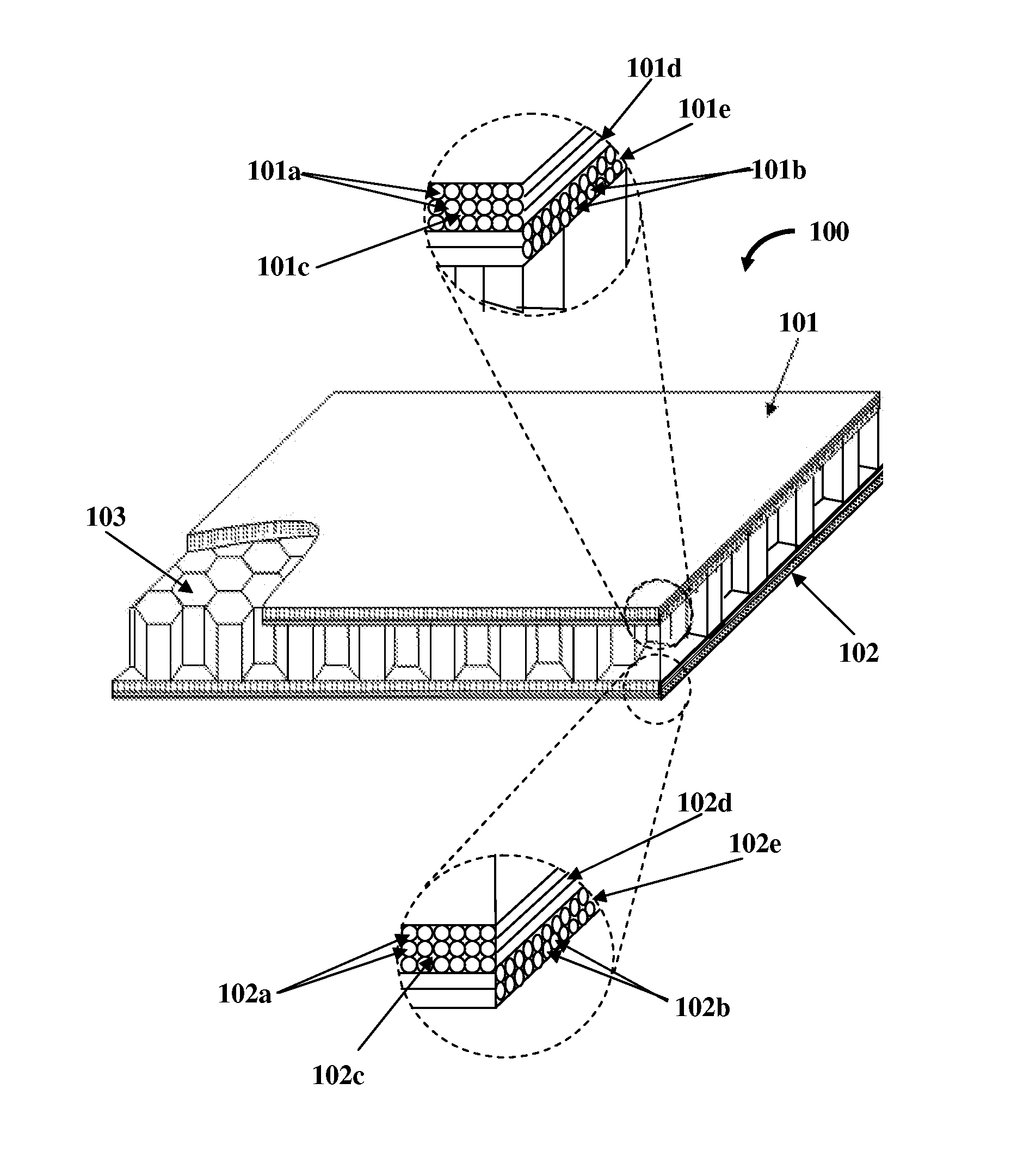
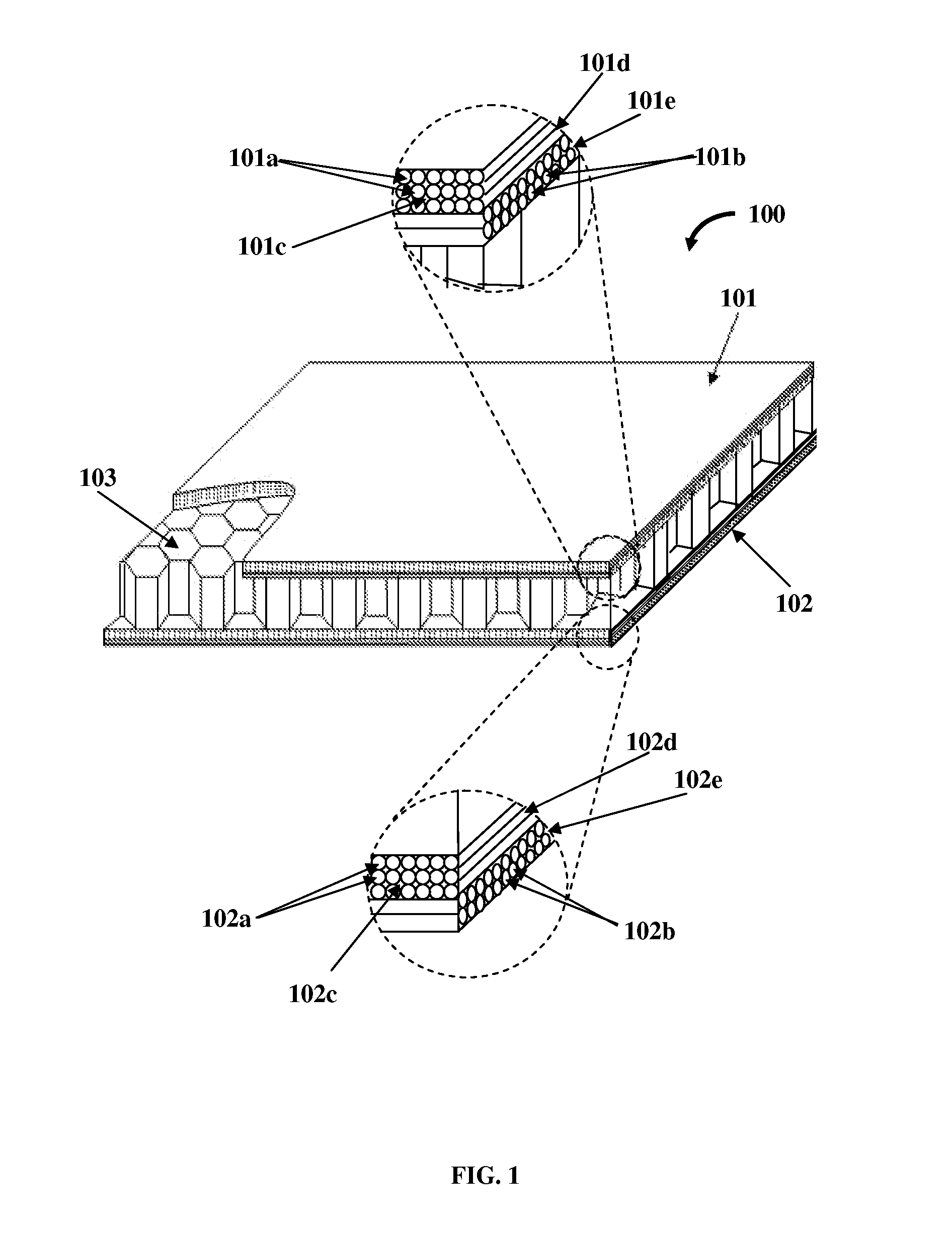
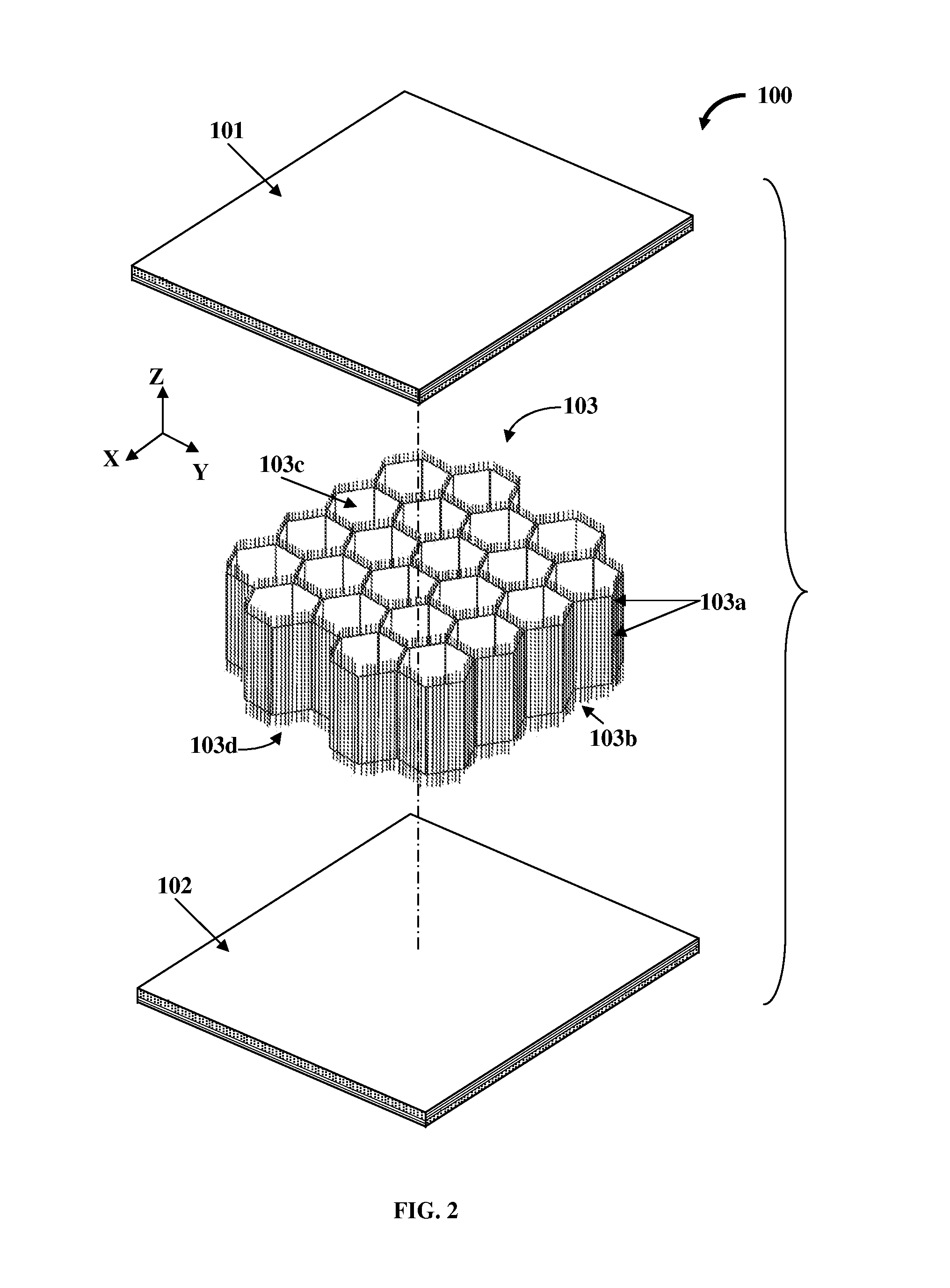
[0019]FIG. 1 illustrates a perspective view of a radiolucent patient table top 100. The radiolucent patient table top 100 disclosed herein comprises a first face sheet 101, a second face sheet 102, and a carbon fiber honeycomb core 103. The first face sheet 101 comprises carbon fibers 101a and 101b in a first radiolucent plastic matrix 101c. The second face sheet 102 comprises carbon fibers 102a and 102b in a second radiolucent plastic matrix 102c. In an embodiment, the first plastic matrix 101c of the first face sheet 101 and the second plastic matrix 102c of the second face sheet 102 comprise, for example, a radiolucent epoxy resin. The carbon fiber honeycomb core 103 is disposed between the first face sheet 101 and the second face sheet 102. The first face sheet 101 and the second face sheet 102 sandwich the carbon fiber honeycomb core 103. The honeycomb core 103 comprises carbon fibers 103a embedded in a third radiolucent plastic matrix 103b as exemplarily illustrated in FIGS. 2...


PUM


Abstract

A radiolucent patient table top including a first face sheet, a second face sheet, and a honeycomb core is provided. The first face sheet includes carbon fibers in a first radiolucent plastic matrix. The second face sheet includes carbon fibers in a second radiolucent plastic matrix. The honeycomb core is disposed between the first face sheet and the second face sheet, where the first face sheet and the second face sheet sandwich the honeycomb core. The honeycomb core includes carbon fibers embedded in a third radiolucent plastic matrix.

Description

CROSS-REFERENCE TO RELATED APPLICATIONS[0001]This application claims priority to and the benefit of provisional patent application number 2424 / CHE / 2014 titled “Radiolucent Patient Table”, filed in the Indian Patent Office on May 15, 2014, and non-provisional patent application number 2424 / CHE / 2014 titled “Radiolucent Patient Table”, filed in the Indian Patent Office on May 11, 2015. The specifications of the above referenced patent applications are incorporated herein by reference in their entirety.BACKGROUND[0002]The apparatus disclosed herein, in general, relates to a composite structure, and more specifically, relates to a radiolucent patient table top.[0003]Conventional radiolucent patient tables comprise carbon fiber reinforced plastic (CFRP) skins with a foam core made of, for example, polyurethane or polymethacrylimides. CFRP table tops have twice as much X-ray permissibility as wooden table tops and five times that of plastic table tops. Improved radiolucency results in redu...

Claims


Application Information

Patent Timeline
Patent Type & Authority Applications(United States)
IPC IPC(8): A61B6/04A61G13/10
CPCA61G13/10A61B6/0442
Inventor ARAVAMUDAN, GOSAKAN
Owner ARAVAMUDAN GOSAKAN
Learn More