Assembly comprising an implantable part designed to be fastened to one or more bones or bone portions to be joined, and at least one screw for fastening the implantable part to said bone(s)

a technology of implantable parts and assemblies, applied in the field of assembly comprising an implantable part designed, can solve the problems of assembly having a noteworthy risk of unscrewing one or more screws, assembly has a relatively high manufacturing cost, and is not always very effectiv

Active Publication Date: 2015-11-19
FX SOLUTIONS
View PDF3 Cites 58 Cited by
  • Summary
  • Abstract
  • Description
  • Claims
  • Application Information

AI Technical Summary

Benefits of technology

[0018]The plurality of possible implantation directions of the screw results (i) from the presence of said notch, which locally interrupts the tapping of the hole and allows a slight deformation of said implantable part at that hole, (ii) the specific conical shape of the head, and (iii) the lack of narrow engagement of the respective threats of the head of the screw and hole during the first portion of the screwing phase; said effective jamming also results from (i) said possibility of slight deformation allowed by the notch, (ii) the specific conical shape of the head, which allows the respective threads of the head of the screw and the hole to gradually interlock during the second portion of the screwing phase, and which performs that complete interlocking at the end of screwing.
[0021]It was possible to determine these values as optimal to obtain said plurality of implantation and jamming directions of the screw. They allow a possibility of angulation of the axis of the screw in relation to the axis of the hole that may reach 20°.
[0024]The presence of said screw thread in the hole contributes to achieving jamming of the screw in the hole.
[0026]Said slight deformation of the implantable part at that notch is thus made completely possible.
[0030]An angulated orientation of the screw is thus prohibited on the side of the hole opposite that on which said second sector is located. Due to this possibility for selective angulation of the screw, resulting from the arrangement of the notches in carefully chosen locations of the holes, an implantable part may be produced making it possible to protect against the risk of defective implantation of the screw, in particular the risk of a screw emerging at a joint surface of one or more of the treated bones.

Problems solved by technology

In the first case, the base of the plate has the drawback of imposing an implantation direction on the screw and therefore prohibiting implantation directions other than that which is imposed.
Such assemblies also have the drawback of imposing an implantation direction on the screw determined by said engagement.
Furthermore, such assemblies have a noteworthy risk of unscrewing of one or more screws over time under the effect of the repeated forces undergone by the bone(s).
To resolve this risk of unscrewing, various axial retention systems have been designed for the screws, which, in general, have the drawbacks of being relatively expensive to manufacture and not always being very effective.

Method used


Image

  • Assembly comprising an implantable part designed to be fastened to one or more bones or bone portions to be joined, and at least one screw for fastening the implantable part to said bone(s)
  • Assembly comprising an implantable part designed to be fastened to one or more bones or bone portions to be joined, and at least one screw for fastening the implantable part to said bone(s)
  • Assembly comprising an implantable part designed to be fastened to one or more bones or bone portions to be joined, and at least one screw for fastening the implantable part to said bone(s)

Examples


Embodiment Construction

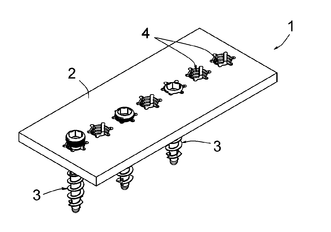
[0047]FIG. 1 shows an assembly 1 comprising an implantable part 2 designed to be fastened to one or more bones or bone portions to be joined, and several screws 3 for fastening said implantable part 2 to said bone(s).

[0048]For the purposes of a purely diagrammatic illustration, the implantable part 2 has been shown in FIG. 1 as a rectangular plate with any shape whatsoever. FIGS. 11 and 12 show that this implantable part may be a base 2 for fastening a glenoid to a shoulder blade 100 or a part forming a convex joint surface called “metaglene” or “glenosphere” (not shown); this implantable part may also be a humeral cortical plate 2 (cf. FIGS. 19 and 20) or cortical plate for the lower end of the radius (cf. FIGS. 21 to 23).

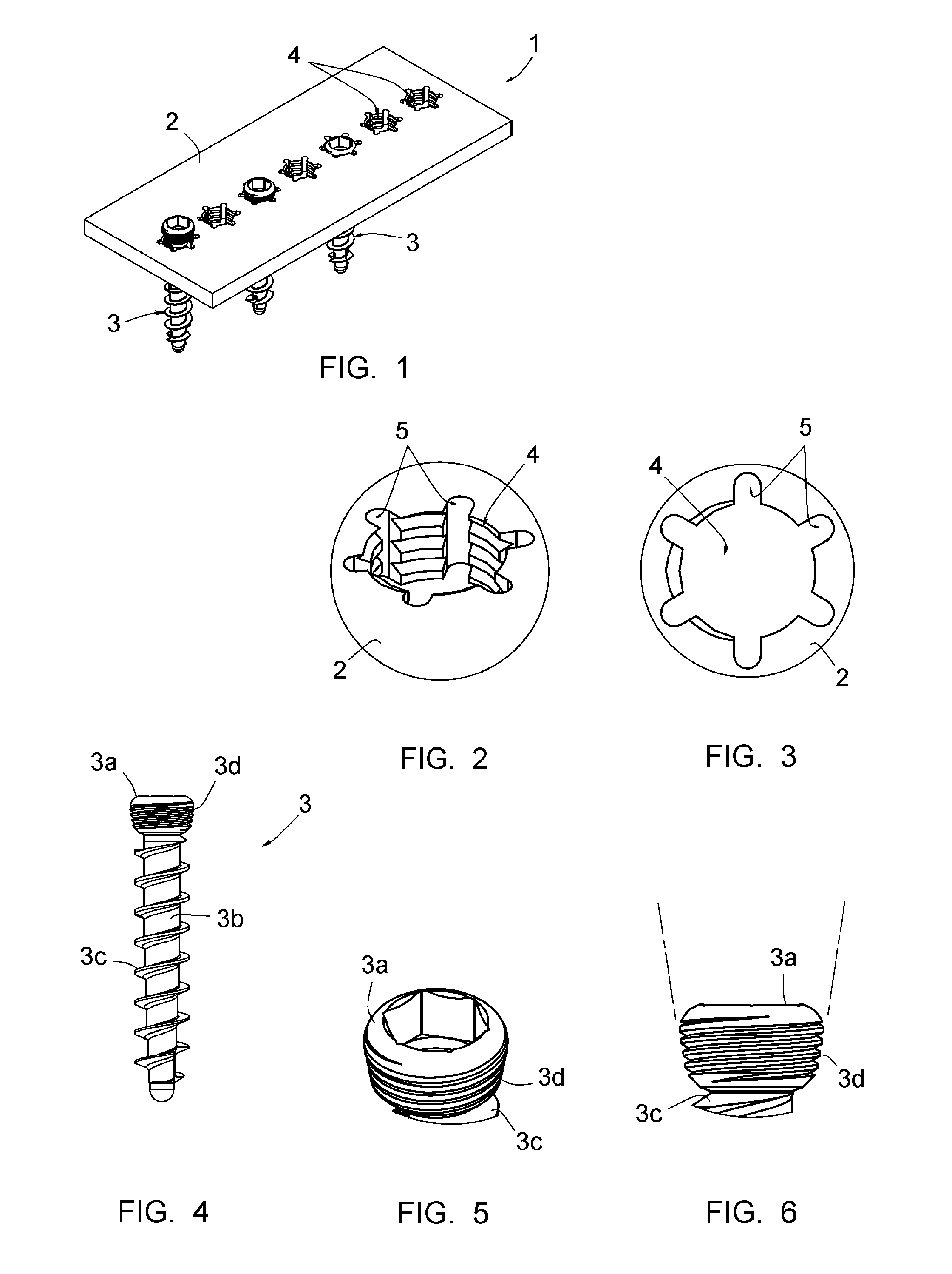
[0049]The plate 2 shown in FIG. 1 comprises a plurality of aligned holes 4, each of which is designed to receive a screw 3.

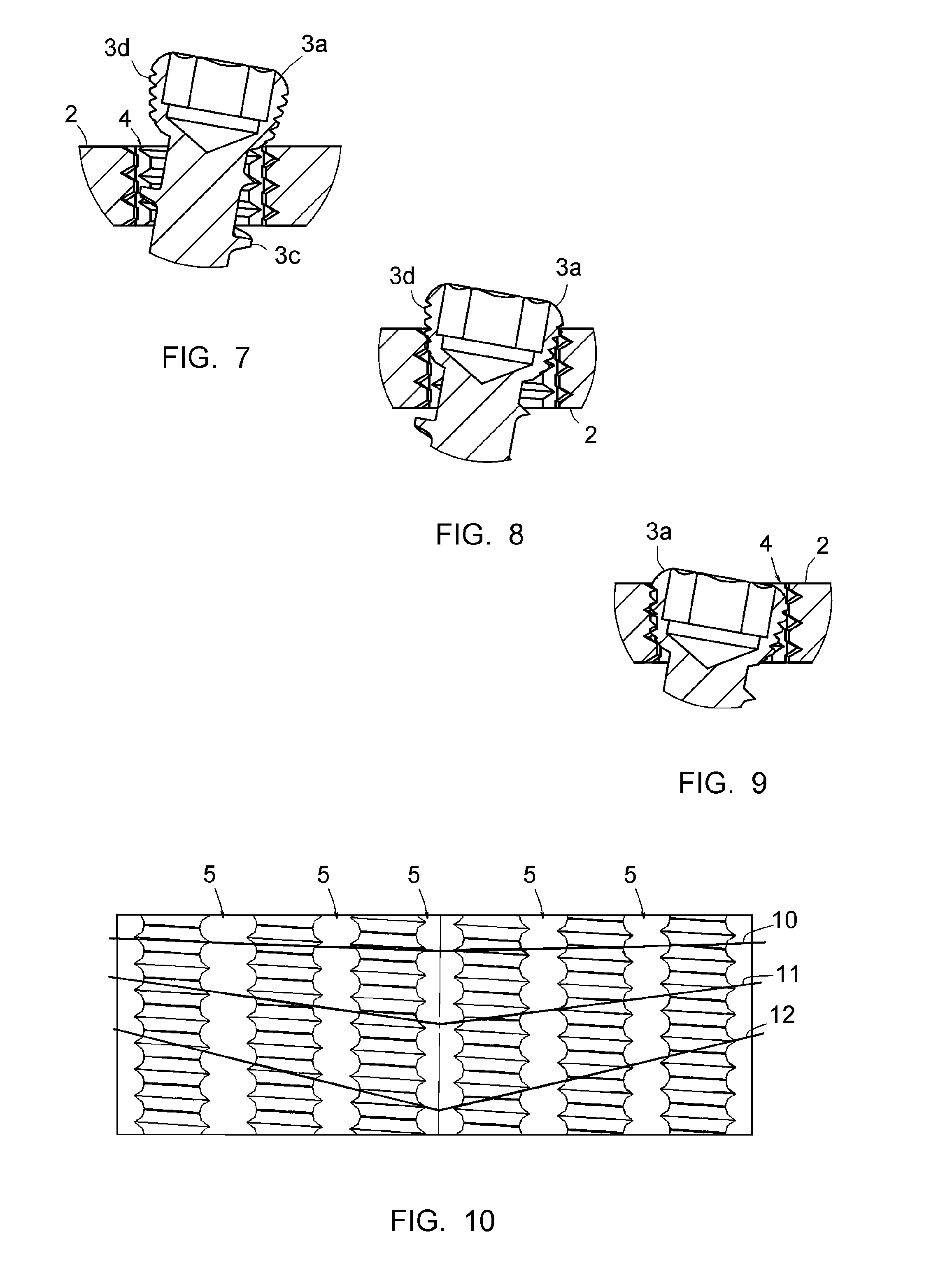
[0050]As shown more particularly in FIGS. 2 and 3, each hole 4 is cylindrical and tapped, and comprises six notches 5 extending radially, reg...


PUM


Abstract

An assembly including an implantable part designed to be fastened to at least one bone or bone portions to be joined and at least one screw for fastening the implantable part to the at least one bone or bone portions. The implantable part includes at least one tapped hole and the screw includes a head designed to be engaged in the tapped hole. The tapped hole is cylindrical and includes at least one radial notch emerging in a surface of the implantable part through which the screw is designed to be engaged in the tapped hole. The radial notch produces an interruption in the tapping included by the tapped hole. The head of the screw is conical, with an apical angle of between 15 and 25°.

Description

CROSS REFERENCE TO RELATED APPLICATION[0001]This application is a Continuation application of U.S. application Ser. No. 13 / 604,798 filed Sep. 6, 2012, pending, entitled ASSEMBLY COMPRISING AN IMPLANTABLE PART DESIGNED TO BE FASTENED TO ONE OR MORE BONES OR BONE PORTIONS TO BE JOINED, AND AT LEAST ONE SCREW FOR FASTENING THE IMPLANTABLE PART TO SAID BONE(S), the content of which is incorporated herein by reference.FIELD OF THE INVENTION[0002]The present invention relates to an assembly comprising an implantable part designed to be fastened to one or more bones or bone portions to be joined, and at least one screw for fastening the implantable part to said bone(s). Said implantable part may in particular be a fastening base for fastening part of a joint prosthesis to a bone, in particular a fastening base for fastening a glenoid to shoulder blade in a total shoulder prosthesis; the implantable part may also be a cortical plate or any other piece of arthrodesis or osteosynthesis equipm...

Claims


Application Information

Patent Timeline
Patent Type & Authority Applications(United States)
IPC IPC(8): A61B17/80A61B17/86
CPCA61B17/8057A61B17/86A61B17/8625A61B17/8615A61B17/8605A61B17/8061A61B17/8066A61B17/863
Inventor MARTIN, JEAN-JACQUES
Owner FX SOLUTIONS
Why Eureka
Try Eureka