Elevator

a technology of elevators and cables, applied in the field of elevators, can solve the problems of difficult control, easy wandering of belt-shaped ropes, etc., and achieve the effects of simple and reliable configuration, low surface roughness, and even surface textur

Active Publication Date: 2015-11-19
KONE CORP
View PDF15 Cites 11 Cited by
  • Summary
  • Abstract
  • Description
  • Claims
  • Application Information

AI Technical Summary

Benefits of technology

[0017]In a preferred embodiment, said circumferential traction surface areas have each a surface roughness or a surface texture substantially different from the roughness or a surface texture, respectively, of the circumferential surface areas of the traction member next to it in said axial direction of the traction member, whereby drifting of the rope away from its circumferential traction surface area to rest against the surface area next to it changes sound and/or vibration produced in the contact area during use, and said means for detecting displacement of one or more of said ropes comprise a sensing arrangement comprising one or more sensors for sensing sound and/or a vibration, which sensing arrangement is arranged to trigger said stopping i.e. the drive machinery to stop the rotation of the traction member if the sound and/or vibration sensed by the sensing arrangement meet predetermined criteria, such as reaches a predetermined limit or changes in a predetermined way. Thus, the displacement of rope(s) can be reacted to effectively with a simple and reliable configuration. Also, this can be carried out gently without damaging the ropes. Preferably, said circumferential traction surface areas are each smoother, such as have a surface roughness lower, or a more even surface texture, than the circumferential surface areas of the traction member next to it in said axial direction of the traction member. In this case, said circumferential surface areas of...

Problems solved by technology

Belt-shaped ropes are prone to wandering in axial direction of the rotatable traction member, ...

Method used


Image

  • Elevator
  • Elevator
  • Elevator

Examples


first embodiment

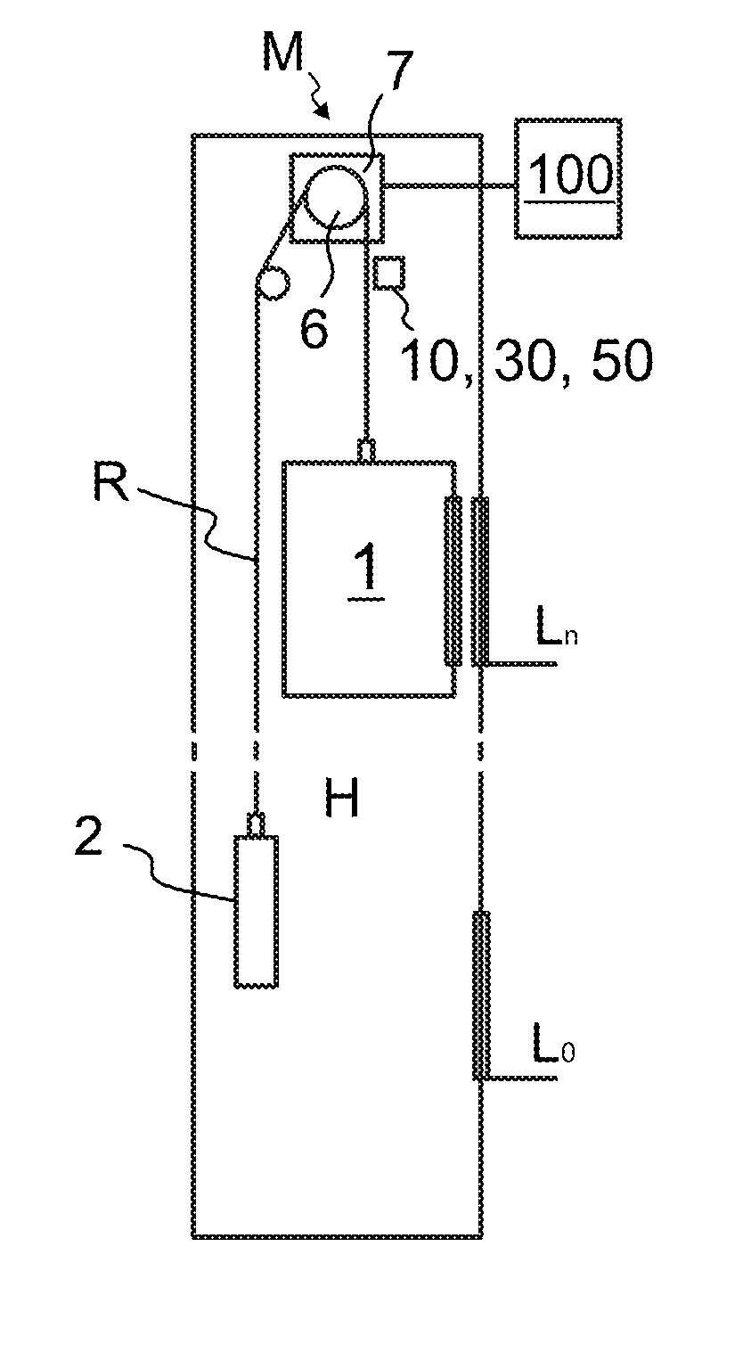
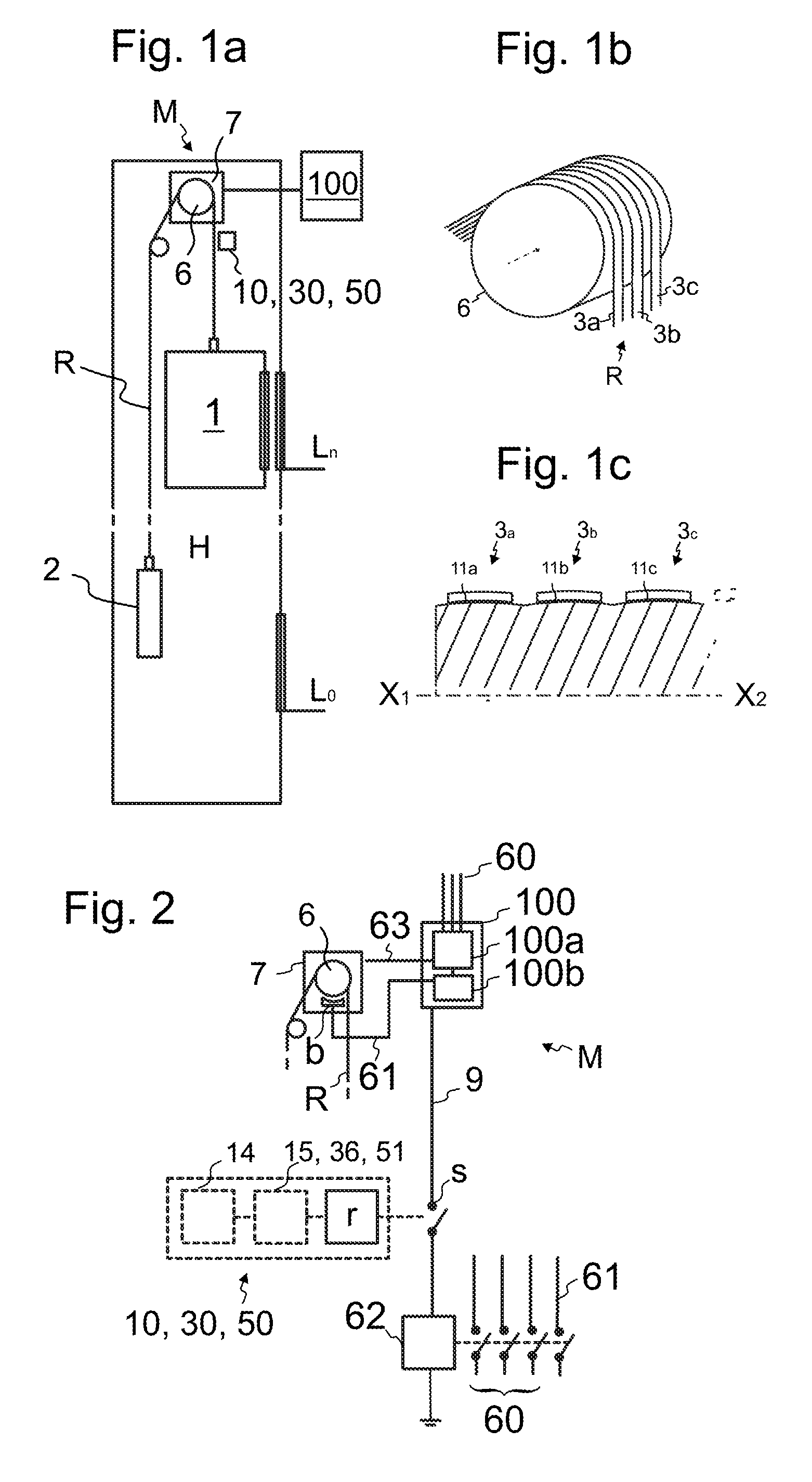
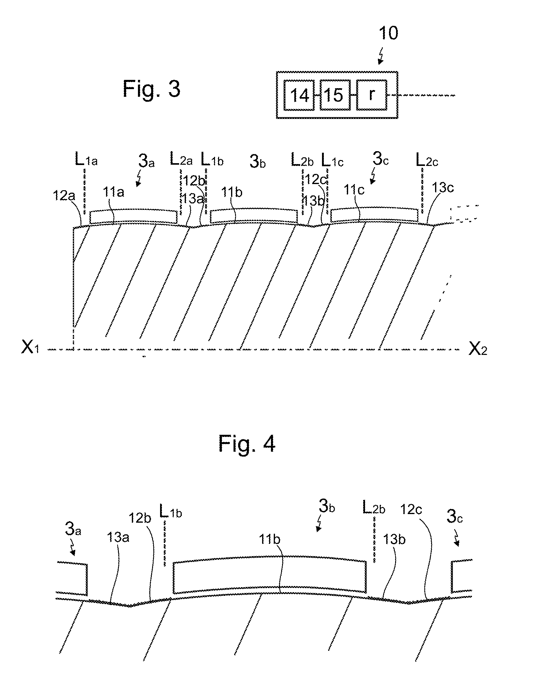
[0048]FIG. 3 illustrates a preferred first embodiment for the means 10,12a-13c for detecting the above mentioned displacement of each of the ropes 3a,3b,3c in axial direction of the rotatable traction member 6. As mentioned, the rotatable traction member 6 comprises a circumferential traction surface area for each of the several ropes 3a, 3b, 3c and each rope 3a,3b,3c is arranged to pass around the rotatable traction member 6 resting against a circumferential traction surface area 11a,11b,11c of the traction member 6. In the preferred embodiment these circumferential traction surface areas 11a,11b,11c have each a surface roughness or a surface texture substantially different than the circumferential surface areas 12a,13a;12b,13b,12c,13c of the traction member 6 next to it in said axial direction of the traction member 6, whereby drifting of the rope 3a,3b,3c away from its circumferential traction surface area 11a,11b,11c to rest against the surface area 12a,13a;12b,13b,12c,13c next ...

second embodiment

[0052]FIG. 5 illustrates a preferred second embodiment for the means for detecting the above mentioned displacement of each of the ropes 3a,3b,3c in axial direction of the rotatable traction member 6. Said means 30 comprise for each rope on opposite sides of the rope 3a,3b,3c in said axial direction of the traction member 6 a first and a second sensing member 31,32; 32, 33; 33,34. In the embodiment as illustrated, there are several ropes whereby there are sensing members which extend between the ropes next to each other. Each sensing member comprises a contact face which the rope next to it can contact when the rope in question is displaced in said axial direction. Each first sensing member 31,32,33 is positioned at the first limit position L1a,L1b,L1c of the rope in question, such that a contact face c thereof is positioned at the point of the limit position L1a,L1b,L1c. Each second sensing member 32,33,34 is positioned correspondingly at the second limit position L2a,L2b,L2c of th...

third embodiment

[0057]FIG. 9a illustrates a preferred third embodiment for the means 50 for detecting the above mentioned displacement of each of the ropes 3a,3b,3c in axial direction of the rotatable traction member 6. Said means 50 comprise sensing devices 52-55 for receiving electromagnetic radiation or ultrasonic sound from said limit positions L1a,L2a;L1b,L2b;L1c,L2c and a monitoring unit 51, connected to the sensing devices and arranged to trigger said drive machinery M to stop the rotation of the traction member 6 if electromagnetic radiation or ultrasonic sound received from one or more of said limit positions L1a,L2a;L1b,L2b;L1c,L2c meet(s) predetermined criteria, such as reaches a predetermined limit or changes in a predetermined way. Each sensing device 52-55 may be in the form of a photocell, infrared, microwave or laser beam sensor, ultrasonic sound sensor for instance. Said sensing devices 52-55 each comprise a receiver for receiving electromagnetic radiation or ultrasonic sound from ...


PUM


Abstract

The invention relates to an elevator comprising
    • a hoistway;
    • an elevator car vertically movable in the hoistway;
    • a plurality of ropes connected to the car;
    • a rotatable traction member comprising a circumferential traction surface area for each of the several ropes;
    • each rope being arranged to pass around the rotatable traction member resting against a circumferential traction surface area of the traction member;
    • drive machinery for controlling rotation of the rotatable traction member.
The elevator comprises means for detecting displacement of each of the ropes over a first limit position of the rope in the first axial direction of the rotatable traction member, and over a second limit position of the rope in the second axial direction of the traction member; and in that
    • displacement of one or more of said ropes in axial direction of the rotatable traction member over the first or second limit position is arranged to trigger the drive machinery to stop the rotation of the rotatable traction member.

Description

[0001]This application claims priority to European Patent Application No. EP14168760 filed on May 19, 2015, the entire contents of which are incorporated herein by reference.FIELD OF THE INVENTION[0002]The invention relates to an elevator. The elevator is particularly meant for transporting passengers and / or goods.BACKGROUND OF THE INVENTION[0003]An elevator typically comprises a hoistway, and an elevator car and a counterweight movable in the hoistway. The elevator further comprises a rotatable traction member, such as a traction wheel, engaging ropes connected to the car. The ropes pass around the rotatable traction member and suspend at least the elevator car and the counterweight. For controlling rotation of the rotatable traction member, the elevator comprises a drive machinery, which typically comprises a motor for rotating the rotatable traction member, a control unit for controlling the motor, as well as a brake for braking rotation of said rotatable traction member. Force f...

Claims


Application Information

Patent Timeline
IPC IPC(8): B66B1/32B66B7/06B66B5/02B66B9/00
CPCB66B1/32B66B5/02B66B7/062B66B9/00B66B5/00B66B7/06B66B7/1215B66B5/022B66B5/0031
Inventor LEHTINEN, HANNULAMPINEN, RIKUANTTILA, MARKKUCIUCULESCU, GABRIELSALMI, MARKUSPURANEN, MIKKO
Owner KONE CORP
Why Eureka
Try Eureka