
Capacitive transducer system, capacitive transducer, and acoustic sensor

a capacitive transducer and capacitive technology, applied in the direction of electrostatic transducer microphones, electric transducers, electrical apparatus, etc., can solve the problems of difficult effective cancellation of noise, large size, and hindering the improvement of sn ratio, so as to improve the sn ratio of capacitive transducer systems, the effect of more reliable or simple configuration

Active Publication Date: 2019-09-10
MMI SEMICON CO LTD
View PDF16 Cites 0 Cited by
  • Summary
  • Abstract
  • Description
  • Claims
  • Application Information

AI Technical Summary

Benefits of technology

[0008]One or more embodiments of the present invention improves an SN ratio of a capacitive transducer system, a capacitive transducer, or an acoustic sensor, with a more reliable or simpler configuration.

Problems solved by technology

In such a capacitive transducer, a noise is considered to result from some causes, such as a noise based on Brownian motion of air accumulated between the semiconductor substrate and the vibration electrode film, and this noise may hinder improvement in an SN ratio.
However, when a cause of a noise is inside the microphone, the noise occurs independently in each of the microphones, which makes it difficult to effectively cancel the noise.
However, this technique is disadvantageous in that the size becomes large as the capacitive transducer.
In this case, however, it is considered that a total noise is specified by a root-sum-square value of noises of the respective capacitors, and effectively canceling the noises is difficult.

Method used


Image

  • Capacitive transducer system, capacitive transducer, and acoustic sensor
  • Capacitive transducer system, capacitive transducer, and acoustic sensor
  • Capacitive transducer system, capacitive transducer, and acoustic sensor

Examples


Embodiment Construction

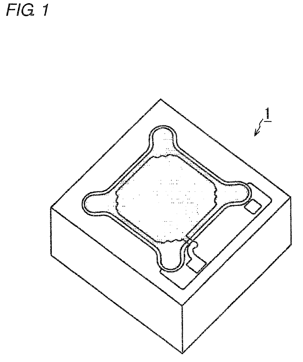
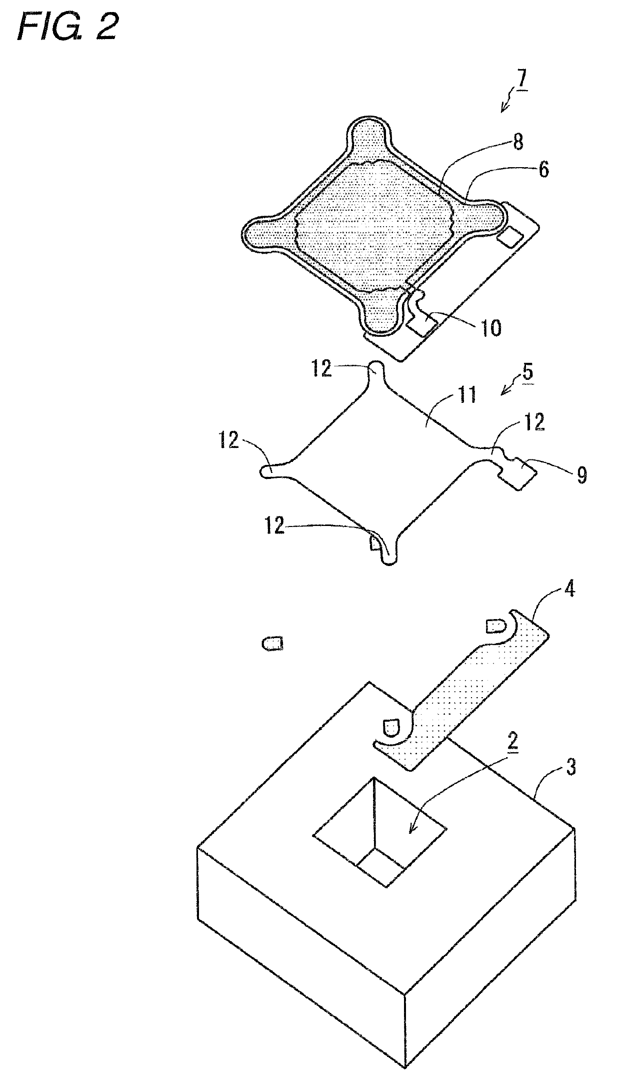
[0042]Hereinafter, embodiments of the present invention will be described with reference to the drawings. Each of the embodiments shown below is an aspect of the present invention, and is not intended to restrict the technical scope of the present invention. In the following, the case of using a capacitive transducer as an acoustic sensor will be described. However, the capacitive transducer according to the present invention is configured to detect displacement of a vibration electrode film, and can thus be used as a sensor other than the acoustic sensor. For example, it may be used as a pressure sensor, or may be used as an acceleration sensor, an inertia sensor, or some other sensor. It may also be used as an element other than the sensor, such as a speaker for converting an electrical signal into displacement. Further, the placement of a back plate, a vibration electrode film, a back chamber, a semiconductor substrate, and the like in the following description is an example. Thi...


PUM


Abstract

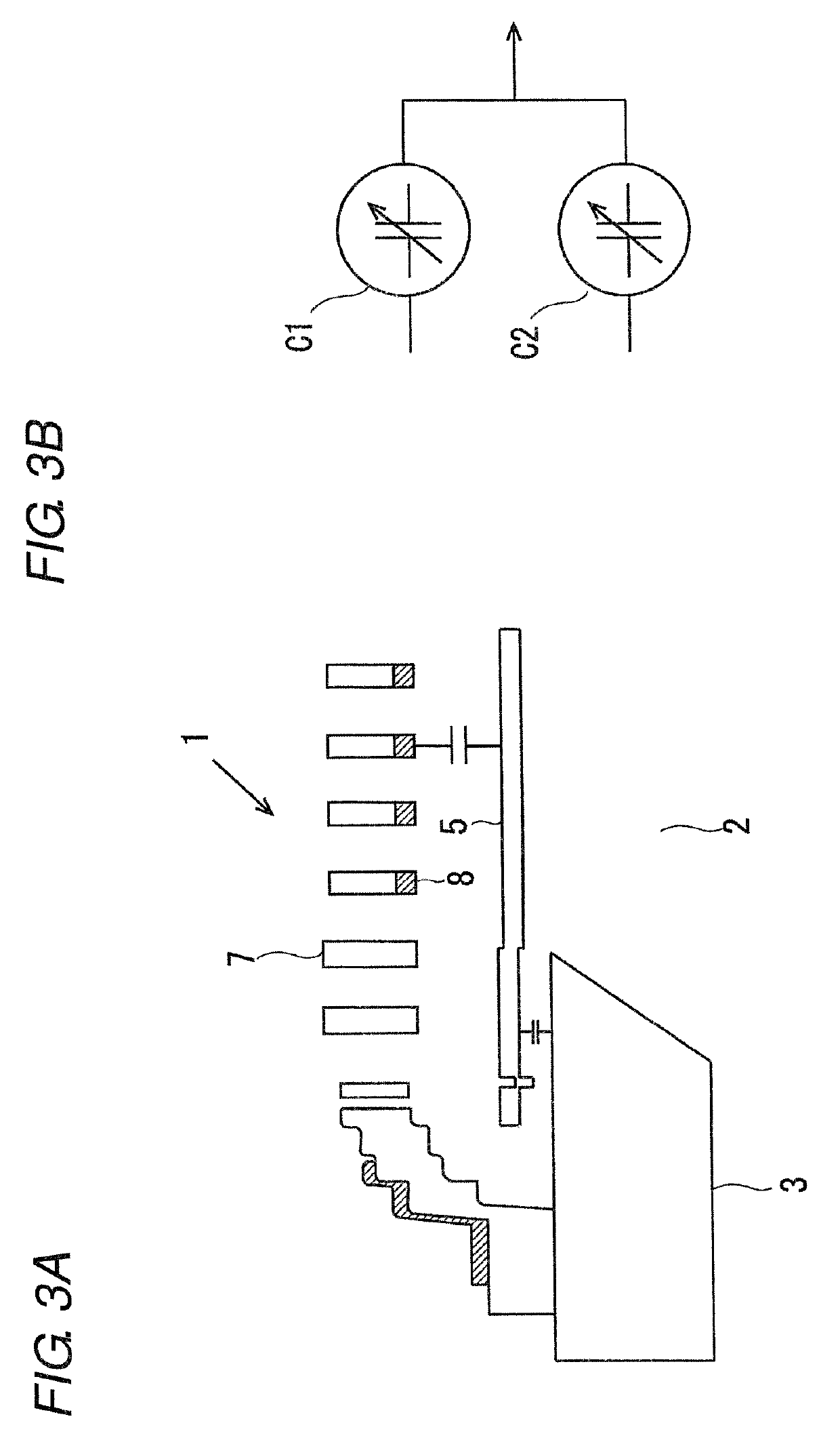
A capacitive transducer system has a capacitive transducer, and a controller. The capacitive transducer includes a first fixed electrode, a second fixed electrode, and a vibration electrode disposed between the first fixed electrode and the second fixed electrode so as to face the first and second fixed electrodes through gaps. A first capacitor is formed by the first fixed electrode and the vibration electrode. A second capacitor is formed by the second fixed electrode and the vibration electrode. The capacitive transducer is configured to convert transformation of the vibration electrode into changes in capacitance in the first capacitor and the second capacitor. The controller is configured to process voltages supplied to the first capacitor and the second capacitor and / or signals based on the changes in capacitance of the first capacitor and the second capacitor.

Description

CROSS-REFERENCE TO RELATED APPLICATION[0001]This application is based on Japanese Patent Application No. 2016-238141 filed with the Japan Patent Office on Dec. 8, 2016, the entire contents of which are incorporated herein by reference.BACKGROUNDField[0002]The present invention relates to a capacitive transducer system, a capacitive transducer, and an acoustic sensor. More specifically, the present invention relates to a capacitive transducer system, a capacitive transducer, and an acoustic sensor, being configured in a capacitor structure formed by the MEMS technique and including a vibration electrode film and a back plate.Related Art[0003]There have hitherto been used a product using an acoustic sensor called an ECM (Electret Condenser Microphone) as a small-sized microphone. However, the ECM is easily affected by heat, and in terms of digitization support and size reduction, a microphone using a capacitive transducer is more excellent, the capacitive transducer being manufactured...

Claims


Application Information

Patent Timeline
Patent Type & Authority Patents(United States)
IPC IPC(8): H04R9/08H04R19/04H04R19/00
CPCH04R9/08H04R19/005H04R19/04H04R2410/03H04R2201/003H04R19/00
Inventor UCHIDA, YUKI
Owner MMI SEMICON CO LTD
Learn More