Sliding member

a sliding member and sliding technology, applied in the field of sliding members, can solve the problems of insufficient loading capacity, low strength of sintered copper based sliding materials of these documents, and inability to completely prevent the corrosion of copper alloy due to organic acids or sulfur contained in the fuel, etc., to achieve high strength, high wear resistance, and high corrosion resistance against organic acids

Active Publication Date: 2015-11-19
DAIDO METAL CO LTD
View PDF3 Cites 5 Cited by
  • Summary
  • Abstract
  • Description
  • Claims
  • Application Information

AI Technical Summary

Benefits of technology

[0008]The present invention has been made in view of the above-described circumstances, and has an object to provide a sliding member having high corrosion resistance as well as a high bonding strength between a porous sintered layer and a resin composition in a sliding layer.
[0033]In the sliding surface side steel phase grain group placed on the sliding surface side of the porous sintered layer among a plurality of stacks of the granular steel phases when observed in a cross-sectional view, an average area ratio of the ferrite phase in the structure of the granular steel phase is not more than 10%, thereby wear resistance of the porous sintered layer is increased. If the resin composition covering the surface of the porous sintered layer wears during the sliding member is used, the granular steel phase in the sliding surface side steel phase grain group is exposed on the sliding surface. Since the granular steel phase in the sliding surface side steel phase grain group is hard due to not more than 10% of the average area ratio of the ferrite phase, the wear resistance of the sliding layer is increased. If the average area ratio of the ferrite phase in the structure of the granular steel phase in the sliding surface side steel phase grain group is more than 10%, an effect of the wear resistance of the sliding layer is reduced. On the other hand, the interface side steel phase grain group placed on the interface side of the porous sintered layer has the average area ratio of the ferrite phase in the structure of the granular steel phase is not more than 20%. Thus, difference in thermal expansion at an interface between the resin composition in the sliding layer and the steel phase in the interface side steel phase grain group is small. This makes it difficult that shearing at the interface therebetween occurs, and increases bonding strength between the resin composition and the granular steel phase. Simultaneously, shearing at an interface between the Ni—P alloy phase and the steel phase in the interface side steel phase grain group can be less likely to occur, and strength of the porous sintered layer is increased.

Problems solved by technology

Although the sintered copper based sliding members of JP-A-2002-180162, JP-A-2013-217493 and JP-A-2013-237898 have corrosion resistance by including Ni, Al and Zn, the corrosion of the copper alloy due to organic acids or sulfur contained in the fuel can not be completely prevented.
Moreover, the sintered copper based sliding materials of these documents have a low strength since they include pores throughout the sliding member, and have an insufficient loading capability especially for a sliding member used for a common rail-type fuel injection pump shown in JP-A-2013-83304 etc.
However, the porous sintered layer composed of a copper alloy is subjected to the corrosion of the copper alloy by organic acids or sulfur contained in the fuel or lubricating oil.

Method used


Image

  • Sliding member
  • Sliding member
  • Sliding member

Examples


first embodiment

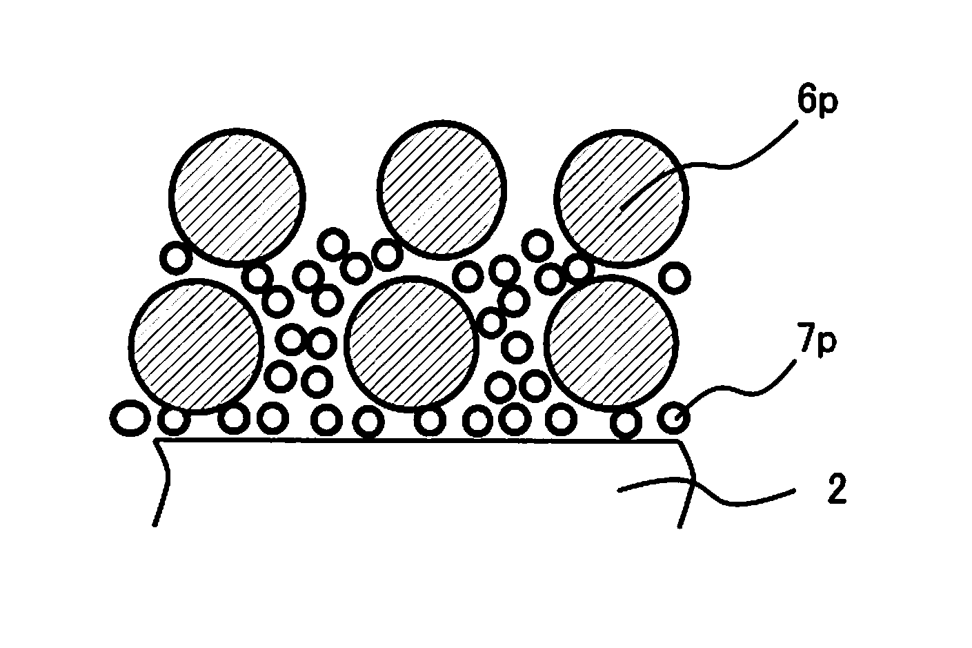
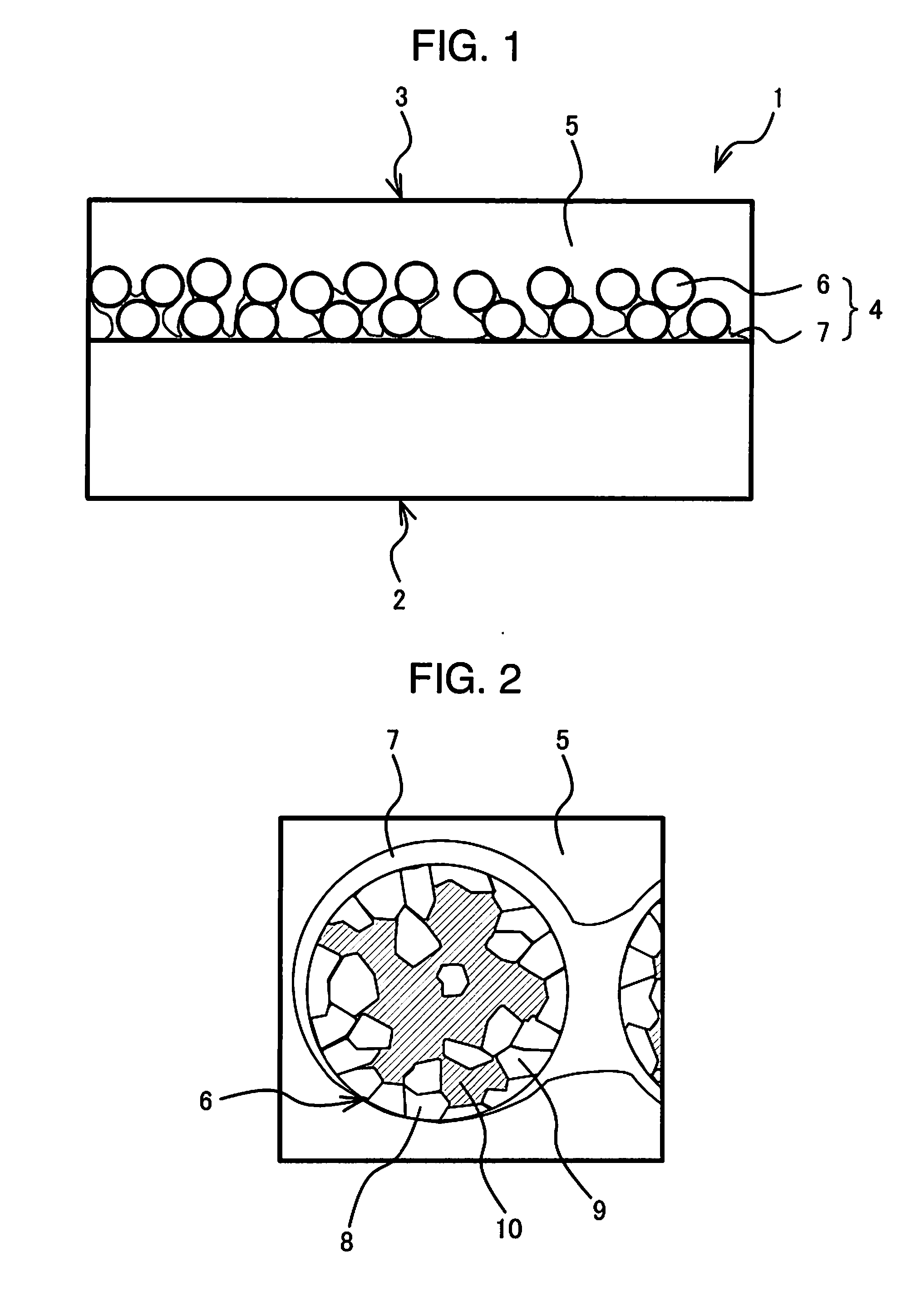
[0047]Next, referring to FIGS. 1 and 2, a sliding member 1 according to a first aspect of the present invention will be described. FIG. 1 is a schematic view showing a cross-section of the sliding member 1 having a sliding layer 3 including a porous sintered layer 4 and a resin composition 5 on a surface of a back metal layer 2. The porous sintered layer 4 includes Ni—P alloy phase 7 and granular steel phase 6. FIG. 2 is an enlarged view showing a structure of the granular steel phase 6.

[0048]As shown in FIG. 1, the sliding member 1 includes the back metal layer 2 and the sliding layer 3, and the sliding layer 3 includes the porous sintered layer 4 on the back metal layer 2 and the resin composition 5 impregnating pores and covering a surface of the porous sintered layer. The porous sintered layer 4 includes granular steel phase 6 and Ni—P alloy phase 7. The Ni—P alloy phase 7 functions as a binder that binds grains of the steel phase 6 with one another and / or binds the grains of th...

second embodiment

[0075]Now, a sliding member 1′ according to a second aspect of the present invention will be described.

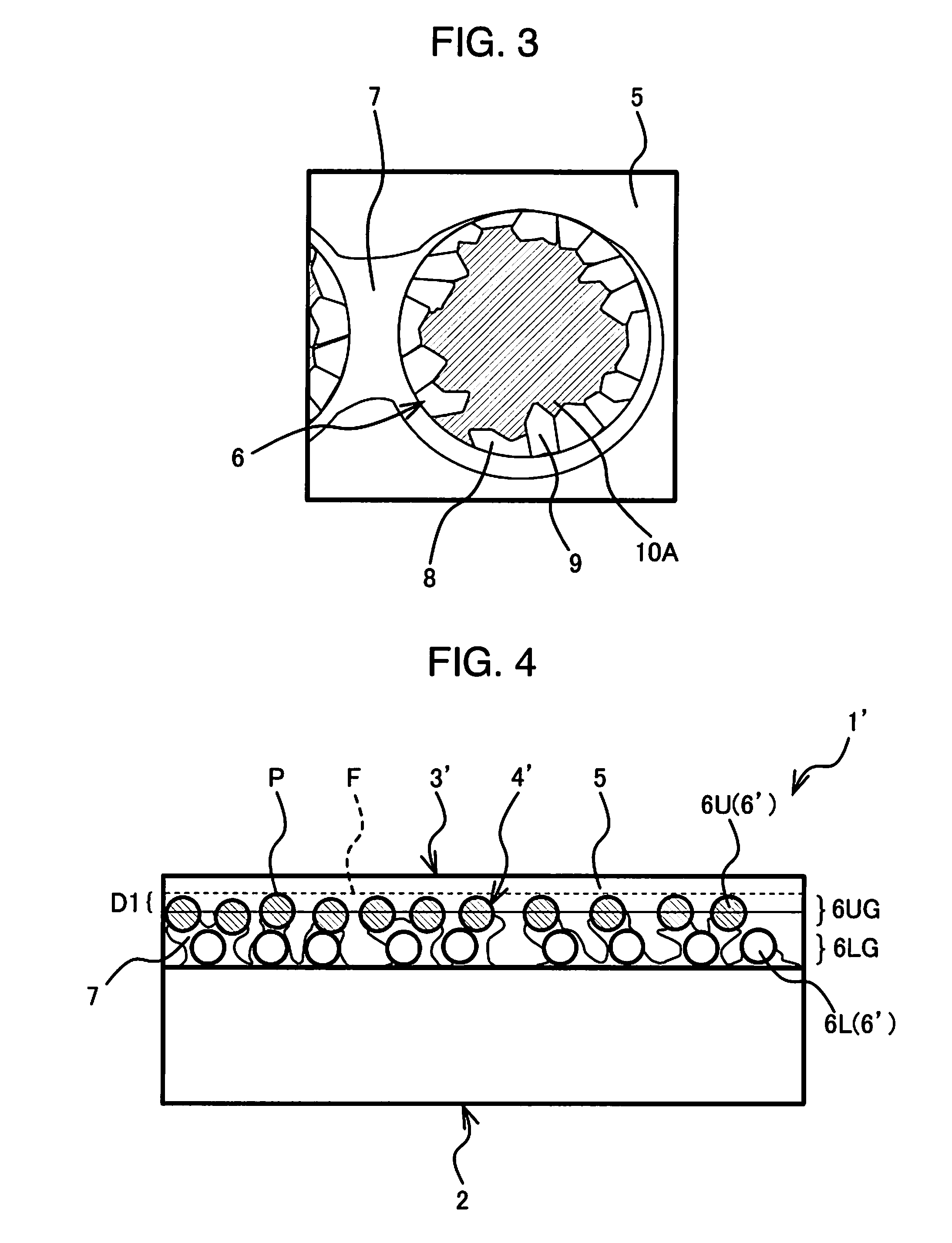
[0076]FIG. 4 is a schematic view showing a cross-section of the sliding member 1′. A sliding layer 3′ including a porous sintered layer 4′ and a resin composition 5′ is formed on a surface of a back metal layer 2. The porous sintered layer 4 includes Ni—P alloy phase 7 and granular steel phase 6′. FIG. 5 is an enlarged view showing a structure of a granular steel phase 6U in a sliding surface side steel phase grain group 6UG. FIG. 6 is an enlarged view showing a structure of a granular steel phase 6L in an interface side steel phase grain group 6LG.

[0077]As shown in FIG. 4, the sliding member 1′ includes the back metal layer 2 and the sliding layer 3′, and the sliding layer 3′ includes the porous sintered layer 4′ on the back metal layer 2 and the resin composition 5 for impregnating pores and covering a surface of the porous sintered layer. The porous sintered layer 4′ includes th...


PUM

PropertyMeasurementUnit
grain sizeaaaaaaaaaa
thicknessaaaaaaaaaa
porosityaaaaaaaaaa

Abstract

Provided is a sliding member having: a back metal layer; and a sliding layer on the back metal layer. The sliding layer includes a porous sintered layer and a resin composition. The sintered layer includes Ni—P alloy phase and granular steel phase made of a carbon steel including 0.3-1.3 mass % of carbon and having a structure of: ferrite phase; and perlite phase, or perlite phase and cementite phase. The Ni—P alloy phase binds the steel phases with one another and / or binds the steel phases with the back metal layer. The steel phase includes a low perlite phase part in a surface. The low perlite phase part has an area ratio of the perlite phase lowered by 50% or more compared with a total area ratio of the perlite phase and the cementite phase at a central part of the steel phase when observed in a cross-section.

Description

BACKGROUND OF THE INVENTION[0001](1) Field of the Invention[0002]The present invention relates to a sliding member having a sliding layer including a porous sintered layer and a resin composition, which has high corrosion resistance and high bonding strength between the resin composition and the porous sintered layer.[0003](2) Description of Related Art[0004]Sintered copper based materials having a porosity of approximately 5-25% have been conventionally used for a sliding member of a fuel injection pump. A liquid fuel is supplied from an outer surface side of a cylindrical sliding member to an inner surface (sliding surface) side thereof through pores existing in the sliding member, and the sliding member is provided with a lubricating fluid film of the liquid fuel on the inner surface (sliding surface) to support a high-speed rotating shaft. Such sintered copper materials have a problem that a copper alloy is subjected to corrosion due to organic acids or sulfur contained in the f...

Claims


Application Information

Patent Timeline
Patent Type & Authority Applications(United States)
IPC IPC(8): C10M103/04
CPCC10M103/04B22F7/004C23C30/00F16C33/145F16C2202/52F16C2204/60F16C2240/48F16C2300/22F16C33/104F16C33/1095F16C2202/54F16C2240/06B22F3/11B22F3/26C22C1/0433C22C1/08B22F2998/10B22F2999/00F16C2360/00B32B15/015Y10T428/12569Y10T428/12944Y10T428/12937Y10T428/12556Y10T428/12479Y10T428/26Y10T428/12958Y10T428/12931Y10T428/12972Y10T428/12965Y10T428/265Y10T428/264B22F9/08B22F3/1007B22F2201/01B32B15/043C23C30/005B32B15/18B32B15/08
Inventor IWATA, HIDEKISAITO, YASUSHI
Owner DAIDO METAL CO LTD
Why Eureka
Try Eureka