Method for manufacturing a rolling bearing and rolling bearing manufactured according to such a method

a technology of rolling bearings and manufacturing methods, applied in the direction of manufacturing tools, bearing units, mechanical equipment, etc., can solve the problems of increased cost, inability to weld them directly together, and inability to precisely control axial clearance or pre-load

Inactive Publication Date: 2015-11-19
AB SKF
View PDF22 Cites 6 Cited by
  • Summary
  • Abstract
  • Description
  • Claims
  • Application Information

AI Technical Summary

Benefits of technology

[0012]One object of the present invention is to solve the above described problems and limitations by providing a

Problems solved by technology

When the main portion and the flange are made of high carbon steel because each of them defines a raceway for the balls, it is not possible to weld them directly together.
This induces an increased cost, since the flange must be made in a high carbon steel, which is costly.
Moreover, in case a bearing includes two rows of balls, the axial clearance or pre-load cannot be precisely controlled.
This approach is rather complicated and increases the overall cost of the bearing.
This appr

Method used


Image

  • Method for manufacturing a rolling bearing and rolling bearing manufactured according to such a method
  • Method for manufacturing a rolling bearing and rolling bearing manufactured according to such a method
  • Method for manufacturing a rolling bearing and rolling bearing manufactured according to such a method

Examples


Embodiment Construction

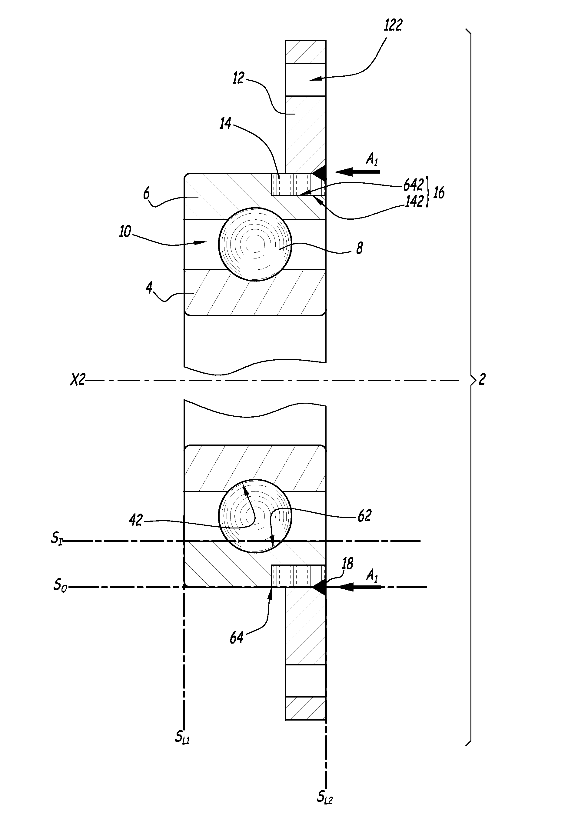
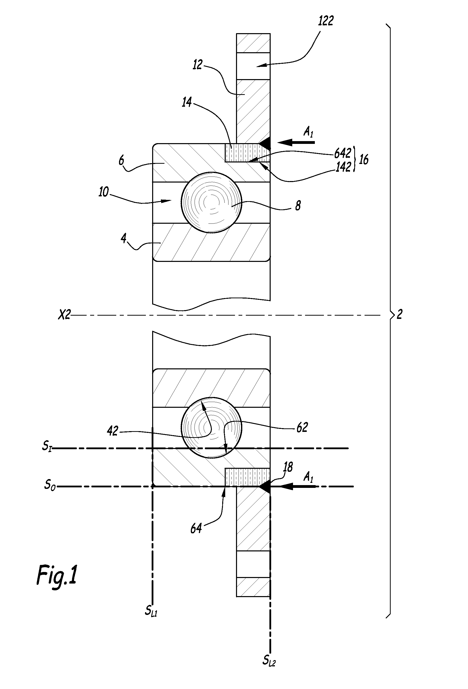
[0041]FIG. 1 discloses a rolling bearing 2 with an inner rotatable ring 4 and an outer non rotatable ring 6. X2 denotes the central axis of bearing 2, which forms a rotation axis for ring 4. A series of balls 8 is located in a rotation chamber 10 defined between rings 4 and 6. Inner ring 4 defines an inner raceway 42 and outer ring 6 defines an outer raceway 62. These raceways are used to guide balls 8 within rotation chamber 10.

[0042]Rings 4 and 6 are made of high carbon steel, that is of a steel which includes a relatively high percentage of carbon, in the range 0.5-1.1% by weight. Such a high carbon steel can successfully undergo a heat treatment which is necessary to harden raceways 42 and 62. For example, the material of rings 4 and 6 can be 100Cr6 steel. Other materials can be used to constitute rings 4 and 6, namely C45, C55, C67, C80, . . .

[0043]Rolling bearing 2 also includes a flange 12 which is provided with several through holes regularly distributed around a central axi...


PUM


Abstract

This method is for manufacturing a rolling bearing having a rotatable ring, a non-rotatable ring, rolling bodies and a flange coupled with a first ring amongst the rotatable ring and non rotatable ring. This method includes at least the following steps: forming the rings and the flange as three independent parts, immobilizing a weldable insert onto the first ring, by electro magnetic pulse technology (EMPT) or by capacitor discharge welding (CW), and welding together the insert and the flange or the insert and a flange holding member. The rolling bearing includes the insert immobilized on the first ring by magnetic pulse welding (MPW), magnetic pulse forming (MPF) or by capacitor discharge welding (CDW). Moreover, the flange or a flange holding member is welded on the insert.

Description

CROSS-REFERENCE TO RELATED APPLICATIONS[0001]This application claims priority to European Patent Application EP13167888 filed on May 15, 2013, the contents of which are herein fully incorporated by reference.TECHNICAL FIELD OF THE INVENTION[0002]The present invention relates to a method for manufacturing a rolling bearing and to a rolling bearing which can be manufactured according to this method.BACKGROUND ART OF THE INVENTION[0003]In the field of rolling bearings, it is known to use high carbon steel, in particular 100Cr6 steel, in order to form the inner and outer rings of a rolling bearing. These rings define raceways which come into contact with the rolling bodies of the rolling bearing, such as balls, needles or rollers and such a type of steel can be hardened at the level of these raceways. Such a type of steel is not weldable.[0004]On the other hand, some rolling bearings must be equipped with a flange in order to immobilize them with respect to their environment, e. g. with...

Claims


Application Information

Patent Timeline
IPC IPC(8): F16C33/58F16C19/08B23K11/26F16C33/62B23K26/20B23K13/01F16C19/06F16C33/64
CPCF16C33/586F16C19/06F16C19/08B23K11/26F16C33/62B23K26/20B23K13/01F16C33/64F16C2226/36F16C2204/66F16C19/184F16C35/067F16C33/60B23K2103/20F16C2204/20F16C2204/62F16C2229/00
Inventor RIBAULT, PATRICE
Owner AB SKF
Why Eureka
Try Eureka