Adjustment housing assembly and monitoring and support system for a rotary feeder in a cellulose chip feeding system for a continuous digester

Active Publication Date: 2015-11-19
ANDRITZ INC
View PDF29 Cites 1 Cited by
  • Summary
  • Abstract
  • Description
  • Claims
  • Application Information

AI Technical Summary

Benefits of technology

The invention is a device that prevents injury and damage to adjusting mechanisms caused by sudden movement of the shaft. It achieves this by placing the mounting and support mechanism inside a hollow adjusting housing, which protects the mechanisms from injury and wear and reduces damage from the environment. The accuracy of the adjustment is also improved as the mechanisms are protected from exposure.

Problems solved by technology

If the clearance is too wide, a pressure loss can occur in the rotary feeder fluid flowing through the rotary feeder, excessive liquid and cellulosic material may flow through the clearance (gap) and accumulate in the housing, e.g., in the end bells of the housing, and excessive liquid may leak through to a low-pressure outlet of the rotary feeder.
If the clearance is too narrow, metal to metal contact may occur between the rotor and chamber and debris caught in the clearance (gap) may etch grooves in the rotor or chamber.
Operator safety and adjustment mechanism accuracy concerns arise when the support mechanisms are located outside the housing.
Operation personnel or others in close proximity to the rotor housing could be injured when the axially moving gearbox is operated without warning.
This situation creates a pinch point where persons could become injured.
Another disadvantage of the support and control mechanisms being on the outside of the rotary housing is the accuracy of the adjustments made.
As the sliding area is exposed to the outside environment, dirt, grime, and elements of the weather can be deposited on the sliding area resulting in obstructions on the metal surface of sliding area.
The obstructions on the metal surface can inhibit the smooth movement of the gearbox on the sliding area and increase the opportunity for personnel injury when trying to clean or remove obstructions.
In addition, exposure to the environment increases the wear of the metal to metal surfaces of the support and control mechanism of prior art systems.

Method used


Image

  • Adjustment housing assembly and monitoring and support system for a rotary feeder in a cellulose chip feeding system for a continuous digester
  • Adjustment housing assembly and monitoring and support system for a rotary feeder in a cellulose chip feeding system for a continuous digester
  • Adjustment housing assembly and monitoring and support system for a rotary feeder in a cellulose chip feeding system for a continuous digester

Examples


Embodiment Construction

[0020]The following detailed description of the exemplary embodiments is presented only for illustrative and descriptive purposes and is not intended to be exhaustive or to limit the scope and spirit of the invention. The embodiments were selected and described to best explain the principles of the invention and its practical application. A person of ordinary skill in the art will recognize many variations can be made to the invention disclosed in this specification without departing from the scope and spirit of the invention.

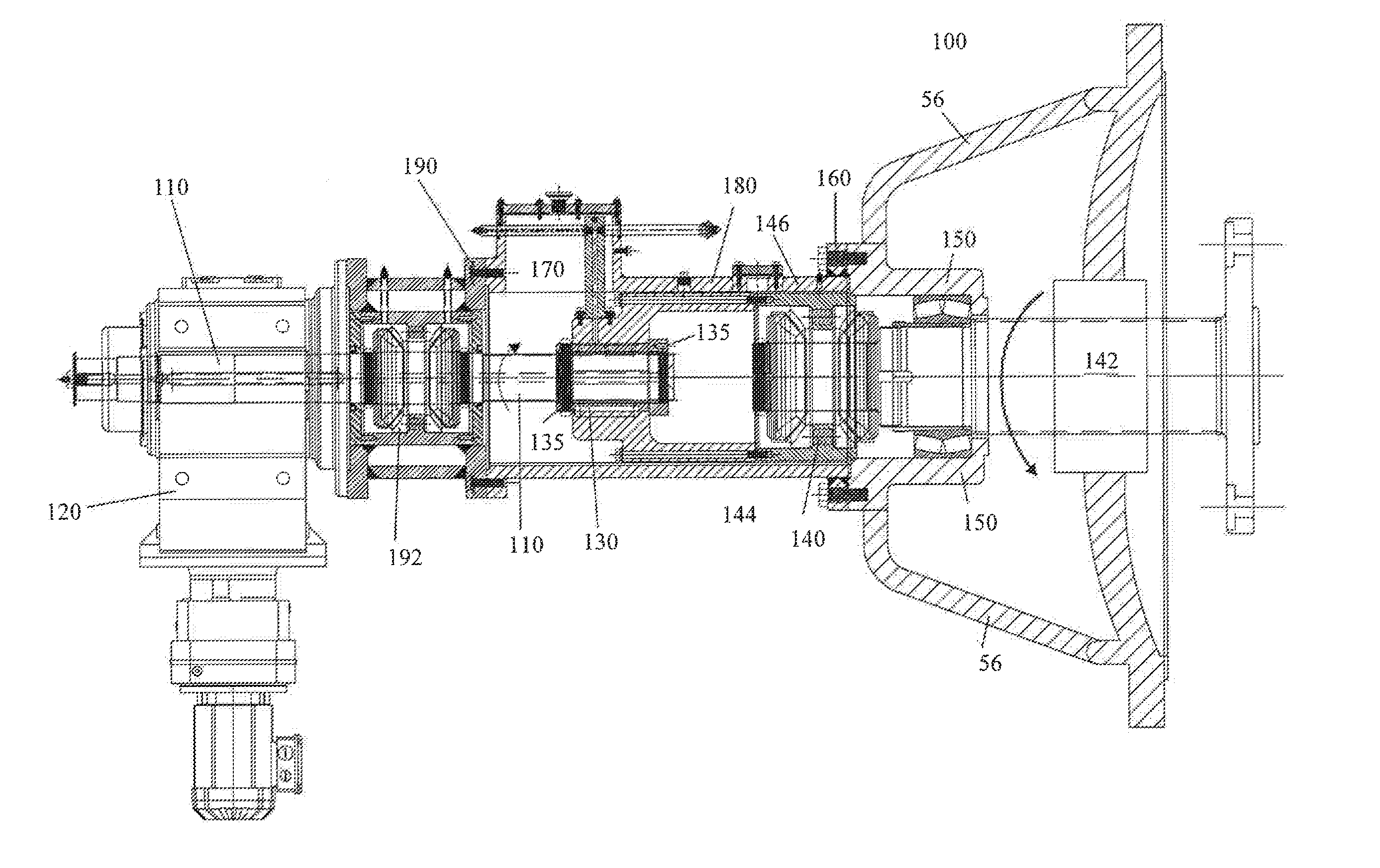
[0021]A rotary feeder typically has the ability to adjust the rotor axially to allow for proper operation of the rotary feeder. Adjusting the rotor axially allows for fluid control and control of the clearance (gap) between the rotary feeder pocket rotor and a housing chamber of the rotary feeder, thereby allowing for pressure changes to be accomplished as the slurry of material flows through the rotary feeder. To control parameters, a rotary feeder adjusting m...


PUM


Abstract

A mounting and support mechanism for a rotary feeder gear motor having an adjusting housing, wherein the adjusting housing includes a support flange adjacent the gear motor, a hollow adjusting housing and a support flange adjacent a stationary feeder end cover. Contained within the adjusting housing is a carrier extension wherein the carrier extension at one end encases a stationary bushing, the stationary bushing houses an adjusting shaft to provide movement of a rotor assembly axially, and at the opposite end the carrier extension connects to a bearing carrier mechanism.

Description

CROSS-RELATED APPLICATION[0001]This application is a Non-Provisional application claiming the benefits of U.S. Provisional Patent Application Ser. No. 61 / 993,513 filed May 15, 2014, the entirety of which is incorporated herein by reference.BACKGROUND OF THE INVENTION[0002]This disclosure relates to a method and system for feeding comminuted cellulosic fibrous material (“chips”) to a treatment vessel, such as a continuous digester, which may produce cellulosic pulp. This disclosure particularly relates to the mounting and support mechanism for adjusting and monitoring a rotary feeder.[0003]Rotary feeders, for example high-pressure feeders (HPFs) and low-pressure feeders (LPFs), asthma feeders, and other similar devices, transfer chips from a chip supply system to a chip processing system, such as a continuous digester system for chemical pulping of wood chips or other cellulosic material. HPFs are described in U.S. Pat. No. 6,669,410 and transfer chips from a low-pressure chip supply...

Claims


Application Information

Patent Timeline
IPC IPC(8): F16M1/00B65G53/46
CPCB65G53/4625F16M1/00D21C7/06
Inventor VOGEL, KEITHSULLIVAN, THOMAS
Owner ANDRITZ INC
Why Eureka
Try Eureka