
Electromagnetic actuator

a technology of electromagnetic actuator and actuator, which is applied in the direction of magnetic bodies, magnets, operating means/releasing devices of valves, etc., can solve the problems of inflexible adaptability, wear of the actuating rod with regard to stability and hardness, and the inability to optimize the material selection of the actuating rod with respect to force transmission capacity and wear of the actuating rod, so as to prevent the magnetic adhesion of the armature

Active Publication Date: 2015-11-19
ROBERT BOSCH GMBH
View PDF25 Cites 10 Cited by
  • Summary
  • Abstract
  • Description
  • Claims
  • Application Information

AI Technical Summary

Benefits of technology

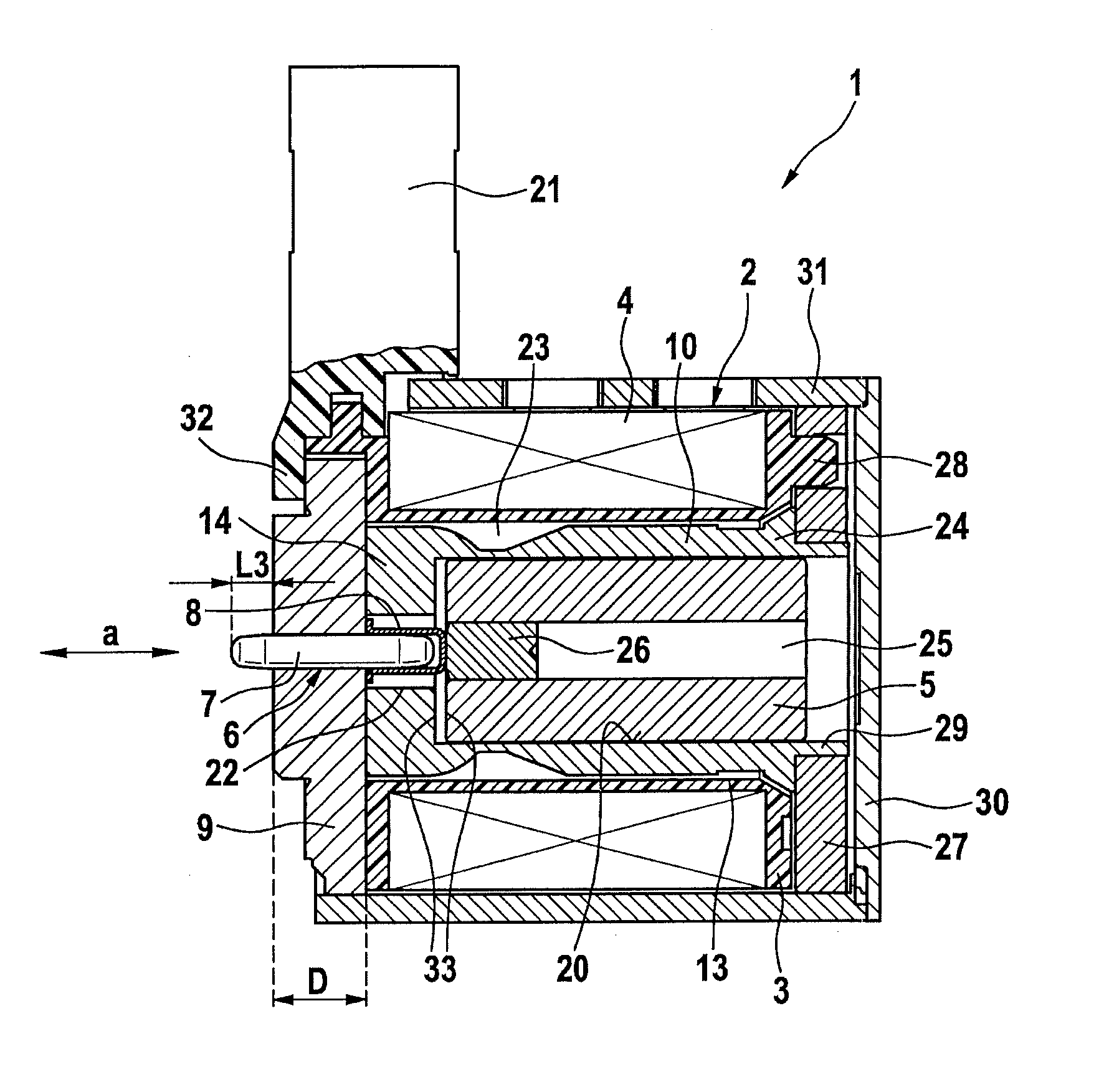
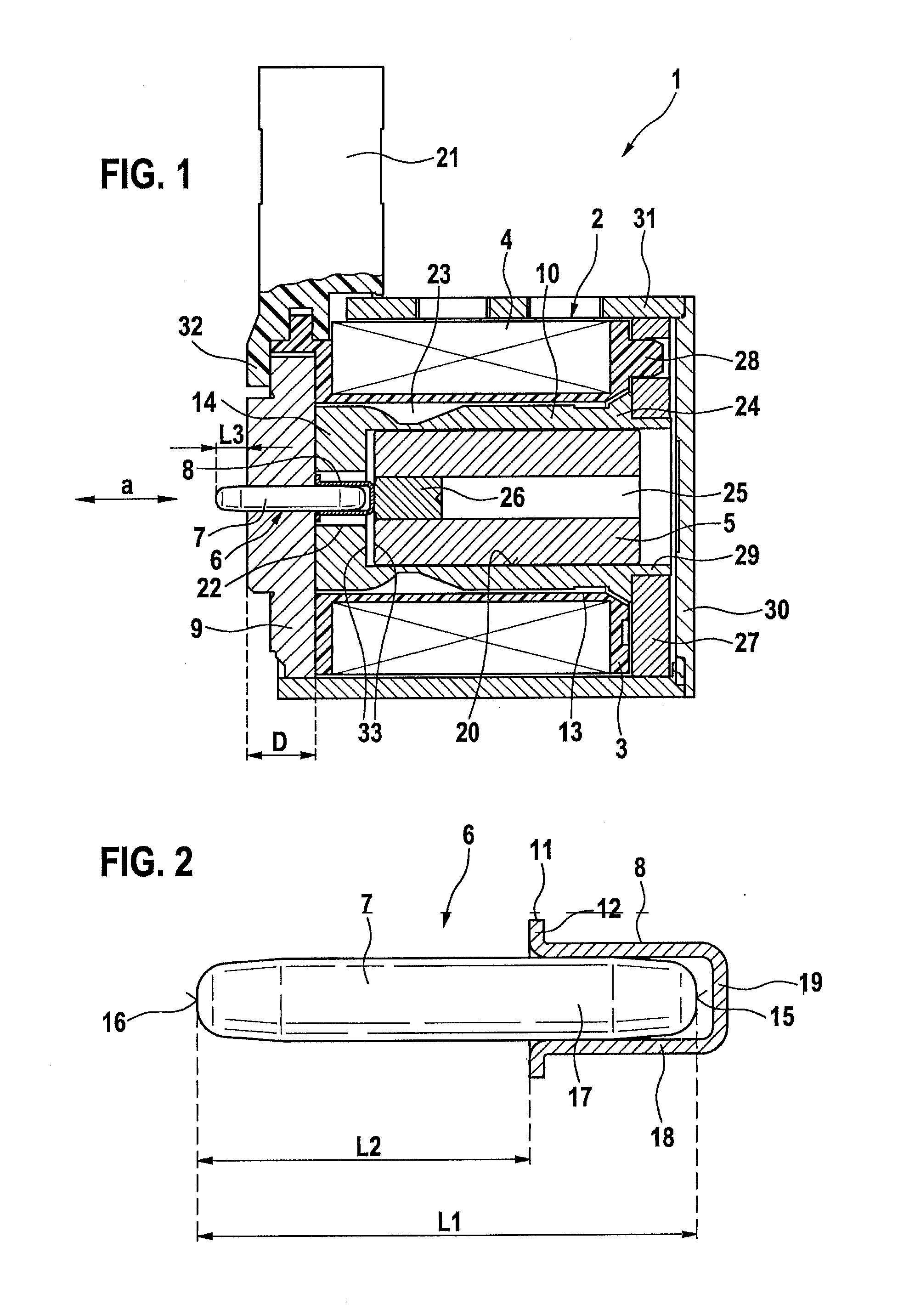
The patent describes an actuator that has a two-part structure, allowing for the use of different materials for the actuating pin and the separator. This results in a more cost-effective and efficient actuator. The actuating pin is made of hardened steel, while the separator is made of non-magnetic steel. The actuating pin has a specific length and the cup-shaped separator is pressed onto it, forming a linear measure. This allows for precise setting of the actuating pin as it comes into contact with the terminal piece or other components. The solenoids used in the electromagnetic actuator often have a position-dependent force, meaning the distance between the collar and the end of the actuating pin plays a crucial role in compensating for any fluctuations in the process. Overall, the actuator described in this patent allows for precise and individual adjustment of the distance measure, resulting in a more efficient and effective actuator.

Problems solved by technology

Since the collar is not formed while the actuating rod is mounted on the armature, but must be produced ahead of time by cutting, it is not possible flexibly to adapt during installation the length of the actuating rod that is protruding from the armature to the individual conditions.
Since the collar for this purpose must be made from non-magnetic material, the entire actuating rod must also be made from non-magnetic material, which has the consequence that the material of the actuating rod cannot be selected in optimized fashion with respect to force transmission capacity and wear with regard to stability and hardness.
This has the consequence that with rising temperature the running clearance required by the actuating rod is reduced and particles present in a gap between the bore and the actuating rod may cause the actuating rod to seize.
Due to the size of the actuating rod, the actuating rod is relatively expensive and causes a considerable pump effect when the armature moves in the bore, which may transport contaminated oil into the magnet.
Because of the fixed connection between the armature and the actuating rod, the sleeve bearing of the actuating rod must additionally absorb magnetic transverse forces, which results in an increased magnetic force hysteresis.
In the known design approach there is additionally the danger that the manufacturing-related eccentricity between the bearing points on the armature and on the actuating rod may cause jamming.
The short bearing, however, has the disadvantage that dirt-sealing effect is clearly reduced.

Method used


Image

  • Electromagnetic actuator
  • Electromagnetic actuator

Examples


Embodiment Construction

[0026]FIG. 1 shows an electromagnetic actuator, which may be used preferably for controlling a slide valve (not shown) for a hydraulic transmission clutch. Such a combination of an electromagnetic actuator and a slide valve is known for example from published international patent application document WO 2011 / 012366 A1, so that no further details will be provided here. The electromagnetic actuator, however, may also be used to actuate another actuator, for example to actuate a shift valve in seat-type construction.

[0027]As may be seen in FIG. 1, the electromagnetic actuator includes a solenoid 1, which is made up of a magnetic coil 2 and an armature 5, and which preferably has a pole tube 10. Magnetic coil 2 has a coil form 3 bearing a coil winding 4, which is developed for example rotationally symmetrically with respect to an axial direction a. Coil form 3 has an electrical terminal 21 projecting from it in the radial direction for example.

[0028]Coil form 3 has a preferably cylindri...


PUM

PropertyMeasurementUnit
forceaaaaaaaaaa
non-magneticaaaaaaaaaa
displacementaaaaaaaaaa

Abstract

An electromagnetic actuator includes: a magnetic coil, which has a coil form having a coil winding situated on it and a central clearance extending in an axial direction; an armature slidably situated in the central clearance; a terminal piece situated on an axial end of the coil form, in which an actuating element is slidably supported in the axial direction. The armature is movable by an actuation of the magnetic coil such that a force applied by the armature is transmitted to the actuating element. The actuating element is configured in two parts, including an actuating pin supported in the terminal piece and a separator fixedly connected to the actuating pin on an end section of the actuating pin protruding from the terminal piece in the direction of the armature and which is acted upon by the armature when the magnetic coil is actuated.

Description

BACKGROUND OF THE INVENTION[0001]1. Field of the Invention[0002]The present invention relates to an electromagnetic actuator having a two-part actuating element.[0003]2. Description of the Related Art[0004]In modern passenger-car automatic transmissions, hydraulically actuated clutches are used for changing gears. In order for the shifting operations to proceed smoothly and imperceptibly for the driver, it is necessary to adjust the hydraulic pressure on the clutches in accordance with predefined pressure ramps with high pressure precision. The pressure required for this purpose may be provided with the aid of hydraulic slide valves, as they are known for example from published international patent application publication WO 2011 / 012366 A1. These slide valves may be actuated either via a pilot valve or directly via an electromagnetic actuator. Electromagnetic actuators may moreover also be used for actuating shift valves, developed as seated valves, in automatic transmissions or oth...

Claims


Application Information

Patent Timeline
Patent Type & Authority Applications(United States)
IPC IPC(8): H01F7/16H01F7/121H01F7/08
CPCH01F7/1607H01F2007/062H01F7/121H01F7/081F16K31/06H01F7/127
Inventor SCHUDT, KLAUS
Owner ROBERT BOSCH GMBH
Learn More