Multilayer inductor device

a multi-layer inductors and inductor technology, applied in the direction of coils, transformers/inductance details, inductances, etc., can solve the problems of low coupling degree between multiple inductors, low coupling degree, and difficulty in achieving low profil

Active Publication Date: 2015-11-19
MURATA MFG CO LTD
View PDF2 Cites 10 Cited by
  • Summary
  • Abstract
  • Description
  • Claims
  • Application Information

AI Technical Summary

Benefits of technology

[0018]According to the present disclosure, it is possible to realize a multilayer inductor device having a high degree of coupling between multiple inductors (choke coils).

Problems solved by technology

However, in the inductor devices having a structure in which the multiple wire-wound choke coils are wound around the common magnetic core, it is not easy to achieve low profile and decrease in size.
However, in the multilayer inductor devices having such a structure in the related art, the respective multiple inductors are generally formed in separate areas when the multilayer inductor device is viewed in plan and the degree of coupling between the multiple inductors is low.

Method used


Image

  • Multilayer inductor device
  • Multilayer inductor device
  • Multilayer inductor device

Examples


Embodiment Construction

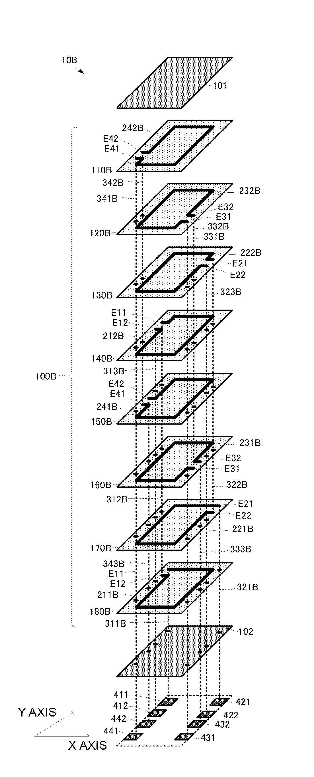
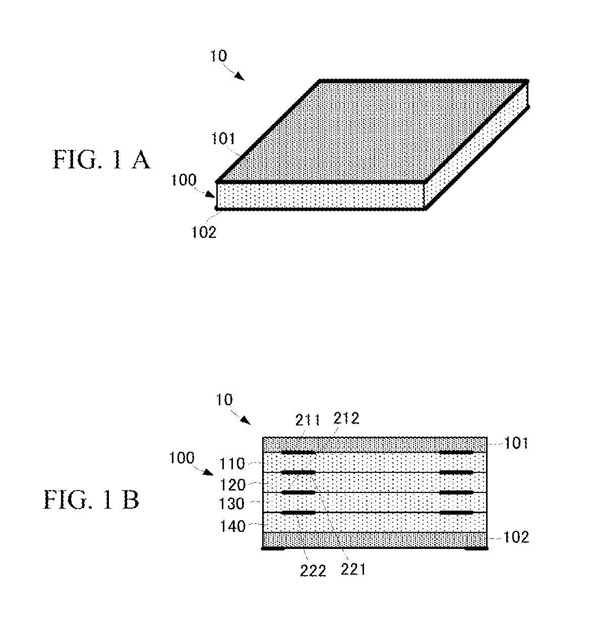
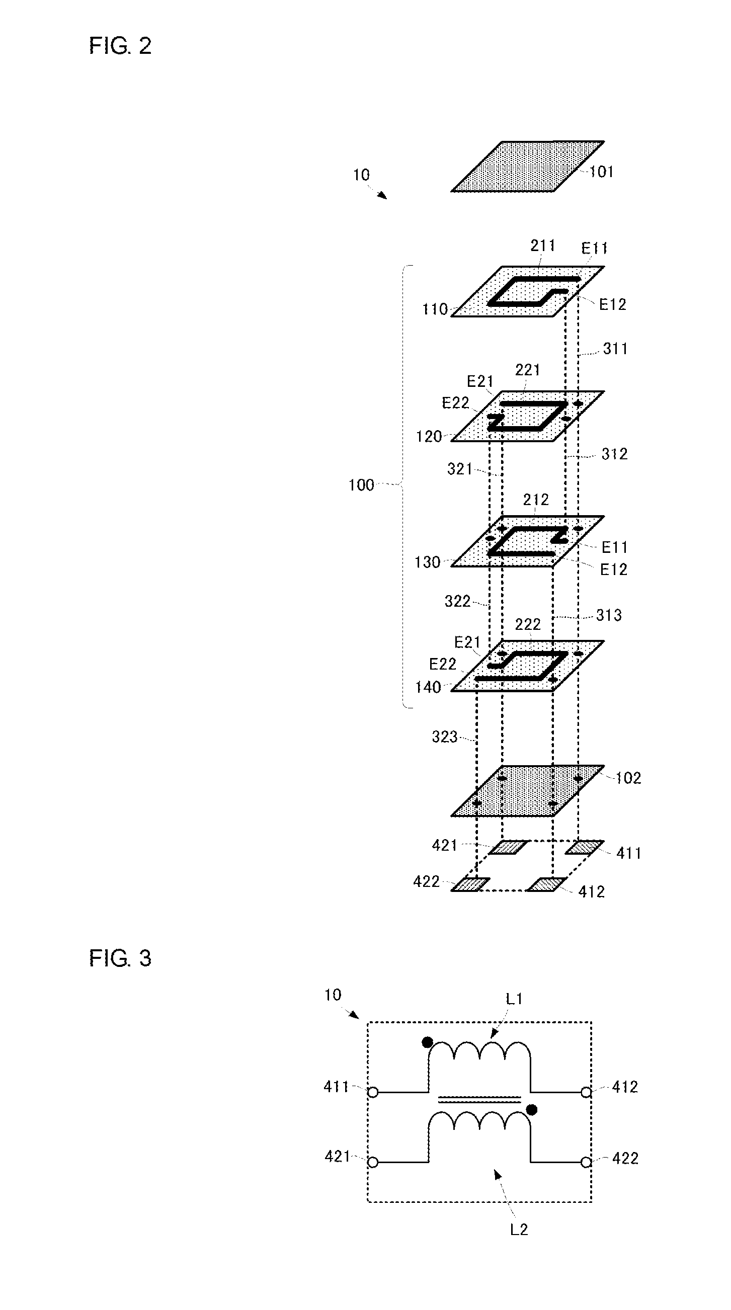
[0029]A multilayer inductor device according to a first embodiment of the present disclosure will now be described with reference to the attached drawings. FIG. 1A is an external perspective view of the multilayer inductor device according to the first embodiment of the present disclosure. FIG. 1B is a conceptual side cross-sectional view illustrating the laminated structure of the multilayer inductor device according to the first embodiment of the present disclosure. FIG. 2 is an exploded perspective view of the multilayer inductor device according to the first embodiment of the present disclosure. FIG. 3 is an equivalent circuit diagram of the multilayer inductor device according to the first embodiment of the present disclosure.

[0030]A multilayer inductor device 10 has a rectangular parallelepiped shape and includes a magnetic multilayer body 100 and non-magnetic layers 101 and 102. The magnetic multilayer body 100 includes magnetic layers 110, 120, 130, and 140. The magnetic lay...


PUM

PropertyMeasurementUnit
magnetic fluxesaaaaaaaaaa
magneticaaaaaaaaaa
drive voltageaaaaaaaaaa

Abstract

A multilayer inductor device (10) includes a magnetic multilayer body (100) in which magnetic layers (110, 120, 130, 140) are laminated in this order. Coil conductors (211, 212) having winding forms are formed on the magnetic layers (110, 130), respectively. The coil conductors (211, 212) are coupled to each other with via conductors (311, 312, 313) to compose a first inductor (L1). Coil conductors (221, 222) having winding forms are formed on the magnetic layers (120, 140), respectively. The coil conductors (221, 222) are coupled to each other with via conductors (321, 322, 323) to compose a second inductor (L2).

Description

BACKGROUND[0001]1. Technical Field[0002]The present disclosure relates to a multilayer inductor device in which multiple coils (inductors) are arranged so as to be coupled to each other with a high degree of coupling.[0003]2. Background Art[0004]Multiphase direct current-direct current (DC-DC) converters disclosed in, for example, Patent Document 1 are currently in widespread use for application of drive voltage of central processing units (CPUs). The multiphase DC-DC converters each use multiple choke coils. These multiple choke coils are required to have a high degree of coupling.[0005]Accordingly, wire-wound choke coils are used as the multiple choke coils used in the multiphase DC-DC converter in the related art. The multiple choke coils are wound around a common magnetic core to increase the degree of coupling.[0006]Patent Document 1: Japanese Unexamined Patent Application Publication No. 2003-284333BRIEF SUMMARY[0007]However, in the inductor devices having a structure in which...

Claims


Application Information

Patent Timeline
Patent Type & Authority Applications(United States)
IPC IPC(8): H01F27/28H01F27/29
CPCH01F27/2804H01F2027/2809H01F27/29H01F27/2823H01F2038/026
Inventor YAZAKI, HIROKAZU
Owner MURATA MFG CO LTD
Why Eureka
Try Eureka