

Litz wire coil
a technology of litz wire and coil, which is applied in the direction of transformer/inductance details, transformer/inductance circuit, inductance, etc., can solve the problems of large number of turns required to obtain the desired coil external diameter, difficulty in increasing inductance, and inability to meet the size requirement of high electrical characteristics, so as to reduce alternating current resistance and limit variations of electrical characteristics
Active Publication Date: 2015-11-19
SWCC SHOWA CABLE SYST CO LTD
View PDF5 Cites 16 Cited by
- Summary
- Abstract
- Description
- Claims
- Application Information
AI Technical Summary
Benefits of technology
The present invention provides a litz wire coil that can improve electrical performance and reduce resistance to alternating current. This makes it suitable for use in non-contact power supplying systems.
Problems solved by technology
However, when the cross sectional flatness ratio (long side / short side) of a litz wire is excessively large as in PTL 1, the number of turns required for obtaining a desired coil external diameter is significantly large.
As a result it is difficult to increase the inductance, and moreover increase in alternating-current resistance results.
As described, today, a litz wire coil that is enough for general use and has high electrical characteristics while satisfying size requirement has not been achieved.
Method used
View moreImage
Smart ImageViewing Examples

Examples
examples
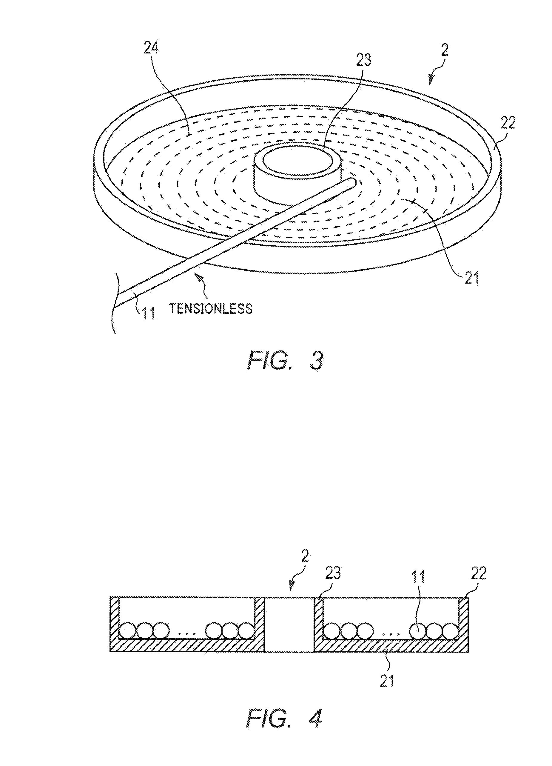
[0055]In Examples, under the condition where coil internal diameter is 200 mm and the number of turns is 35 turns, a litz wire was wound by the manufacturing method of the embodiment to produce a litz wire coil. The external diameter of the coil was adjusted such that the flatness ratio of the litz wire in cross section is 1.10 to 1.60. In Example 1, a litz wire in which the diameter of the element wire is 0.20 mm and the number of twisted is 400 (cross-sectional area: 12.6 mm2) was used. In Example 2, a litz wire in which the diameter of the element wire is 0.11 mm and the number of twisted wires is 1,300 (cross-sectional area: 12.4 mm2) was used.
Login to View More PUM
| Property | Measurement | Unit |
|---|---|---|
| diameter | aaaaa | aaaaa |
| internal diameter | aaaaa | aaaaa |
| external diameter | aaaaa | aaaaa |
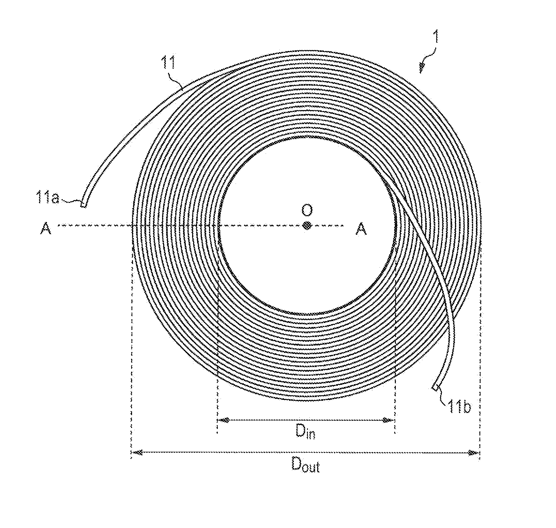
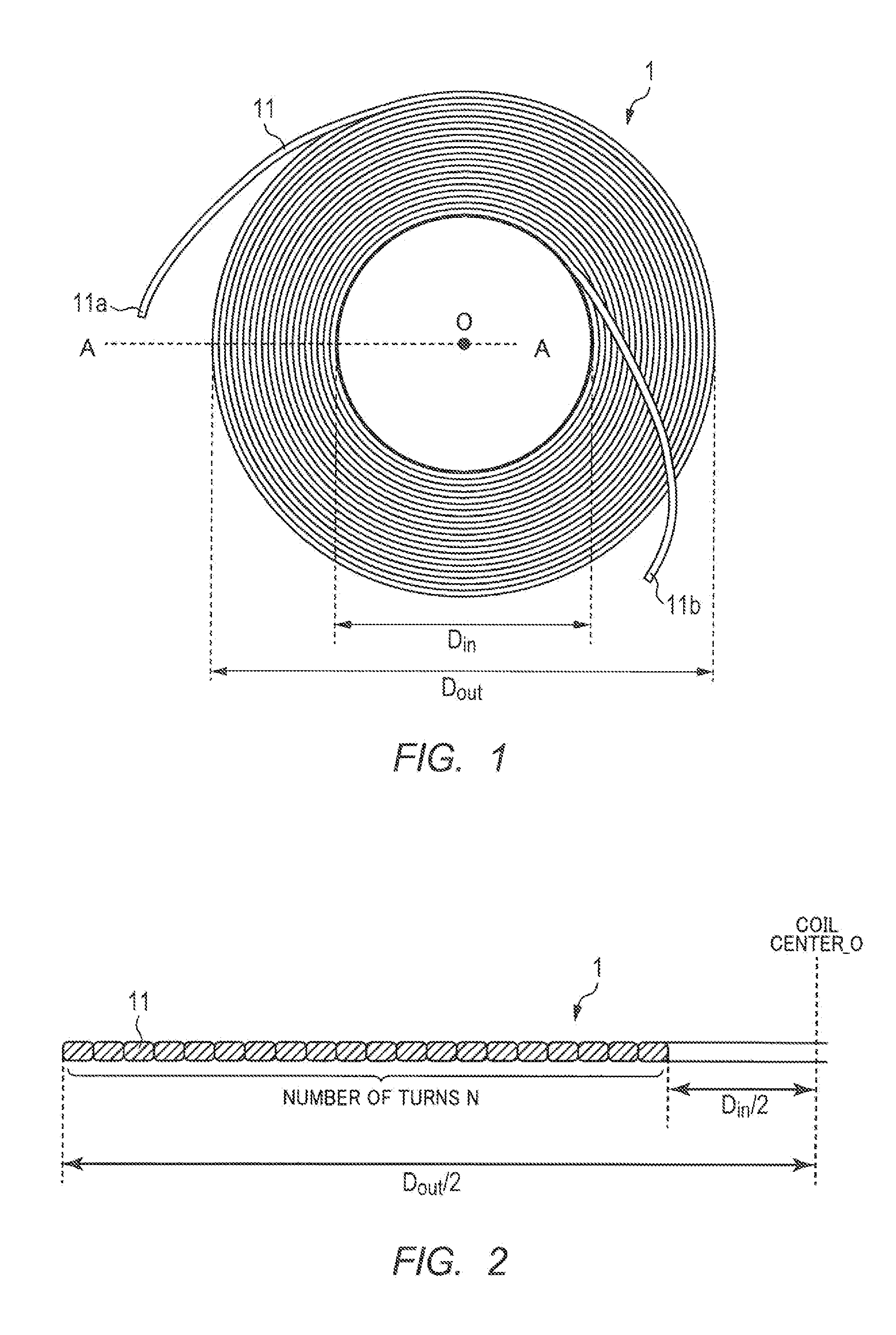
Abstract
Disclosed is a litz wire coil that is configured by spirally winding a litz wire on one plane by a predetermined number of turns. The litz wire is configured by twisting together a plurality of enameled wires formed by baking an insulating film on a conducting body. Pressure shaping is performed such that the litz wire has a substantially rectangular shape in cross section, and the flatness ratio of the litz wire in cross section (long side / short side) is controlled at 1.10 to 1.60, preferably 1.20 to 1.40, more preferably 1.25 to 1.35.
Description
TECHNICAL FIELD[0001]The present invention relates to a litz wire coil suitable for a non-contact power supplying system of an electromagnetic induction type.BACKGROUND ART[0002]In recent years, as a means for charging electric vehicles (EVs), a non-contact power supplying system of an electromagnetic induction type using coils has been studied. A non-contact power supplying system includes an electricity-feeding side coil (primary coil) to which a power is supplied from an alternating current power source, and an electricity-receiving side coil that is disposed to face the electricity-feeding side coil and is magnetically coupled to the electricity-feeding side coil. In a non-contact power supplying system for electric vehicles, an electricity-feeding side coil is disposed outside the vehicle (floor surface), and an electricity-receiving side coil is disposed inside the vehicle.[0003]As an electricity-feeding side coil and an electricity-receiving side coil, a plane coil that is fo...
Claims
Login to View More Application Information
Patent Timeline
 Patent Type & AuthorityApplications(United States)
IPC IPC(8): H01F27/28H01F38/14
CPCH01F38/14H01F27/2823H01F5/00H01F5/02H01F27/2871
InventorHASEGAWA, SHIROUMORI, MASAHIROIIJIMA, TATSUYAMIURA, KIYOSHIKAMIYA, KENJIICHIKAWA, MASAHIRONOZAKI, HIROTO
OwnerSWCC SHOWA CABLE SYST CO LTD