
Dynamic orthosis for foot drop

Inactive Publication Date: 2015-11-26
MP S R L IN CONCORDATO PREVENTIVO
View PDF6 Cites 7 Cited by
  • Summary
  • Abstract
  • Description
  • Claims
  • Application Information

AI Technical Summary

Benefits of technology

The invention allows for a shoe or boot to have a lifting mechanism for the foot during takeoff, adjustable force and adaptability to different foot sizes. It is lightweight, easy to clean and can be used for long periods of time. It can be easily applied inside a shoe, provide accurate positioning of the foot and support it during a step. After the step, the foot can be brought back to its original position by moving the heel close to the static position.

Problems solved by technology

Peripheral paralyses caused by herniated vertebral discs, tumors, degenerative disease of the second neuron and others, are always accompanied by muscle hypotonia and hypotrophy, so that they are called flabby paralyses, and the total loss of motor schemes causes problems for their functional recovery.
All this, from a biomechanical point of view, is cause for a frontal offset of the ankle upon the lifting of the limb from the ground, thereby altering seriously the successive rest phase of the foot.
An automatic response to the deficit of the foot's dorsal flexion is an increment of the hip's flexion upon the lifting phase of the limb, but the vicarious effect is not sufficient, is quite demanding for the patient and, besides, it does not change the pathologic inter-rotation of the ankle.
The drawback of all the elastic systems presently known, lies in the sudden and anti-physiological thrust exerted for lifting the foot upon detachment thereof from the ground, a thrust which, if it is ill supported in case of flabby paralysis, becomes counterproductive in case of spastic paralysis inasmuch as it induces an increase of the muscle hypertonia and the onset of pathologic clones.
Moreover, all these elastic systems are disposed in the posterior side of leg and foot and are unable to control the inversion of the ankle.

Method used


Image

  • Dynamic orthosis for foot drop
  • Dynamic orthosis for foot drop
  • Dynamic orthosis for foot drop

Examples


Embodiment Construction

[0011]The orthosis of the present invention is shown for reference in the accompanying drawings, wherein:

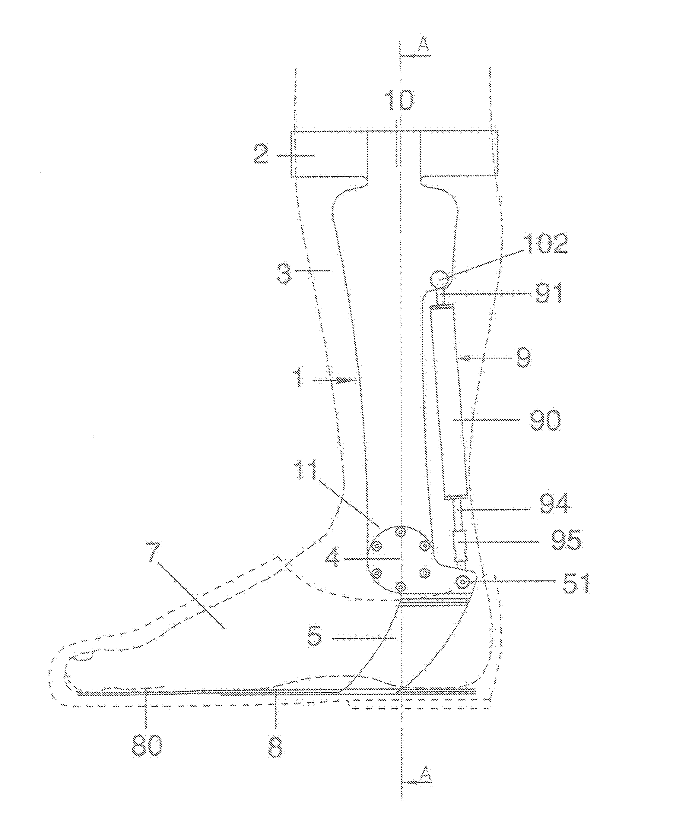
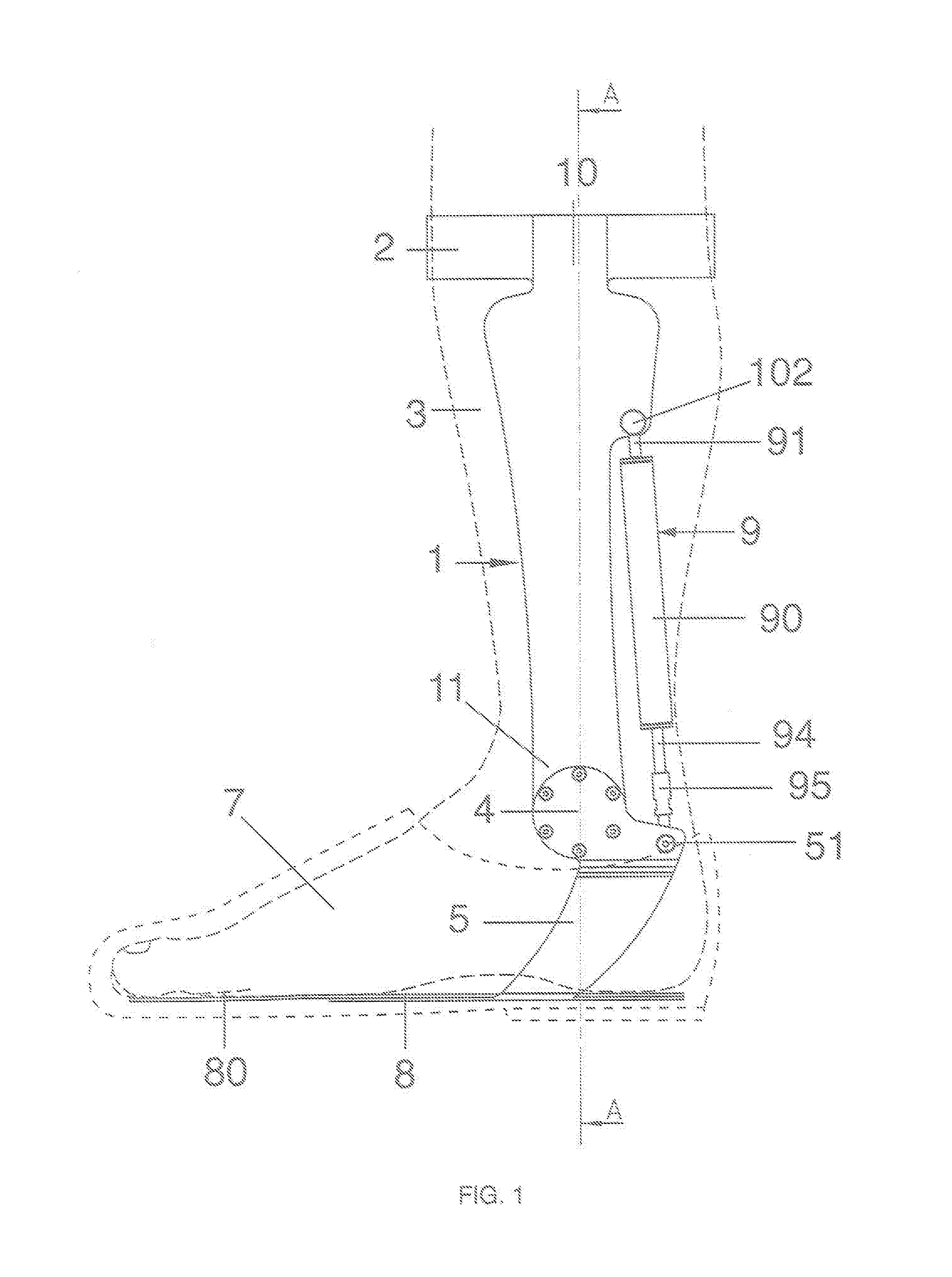
[0012]FIG. 1 is an ensemble front view of the orthosis in the state of use;

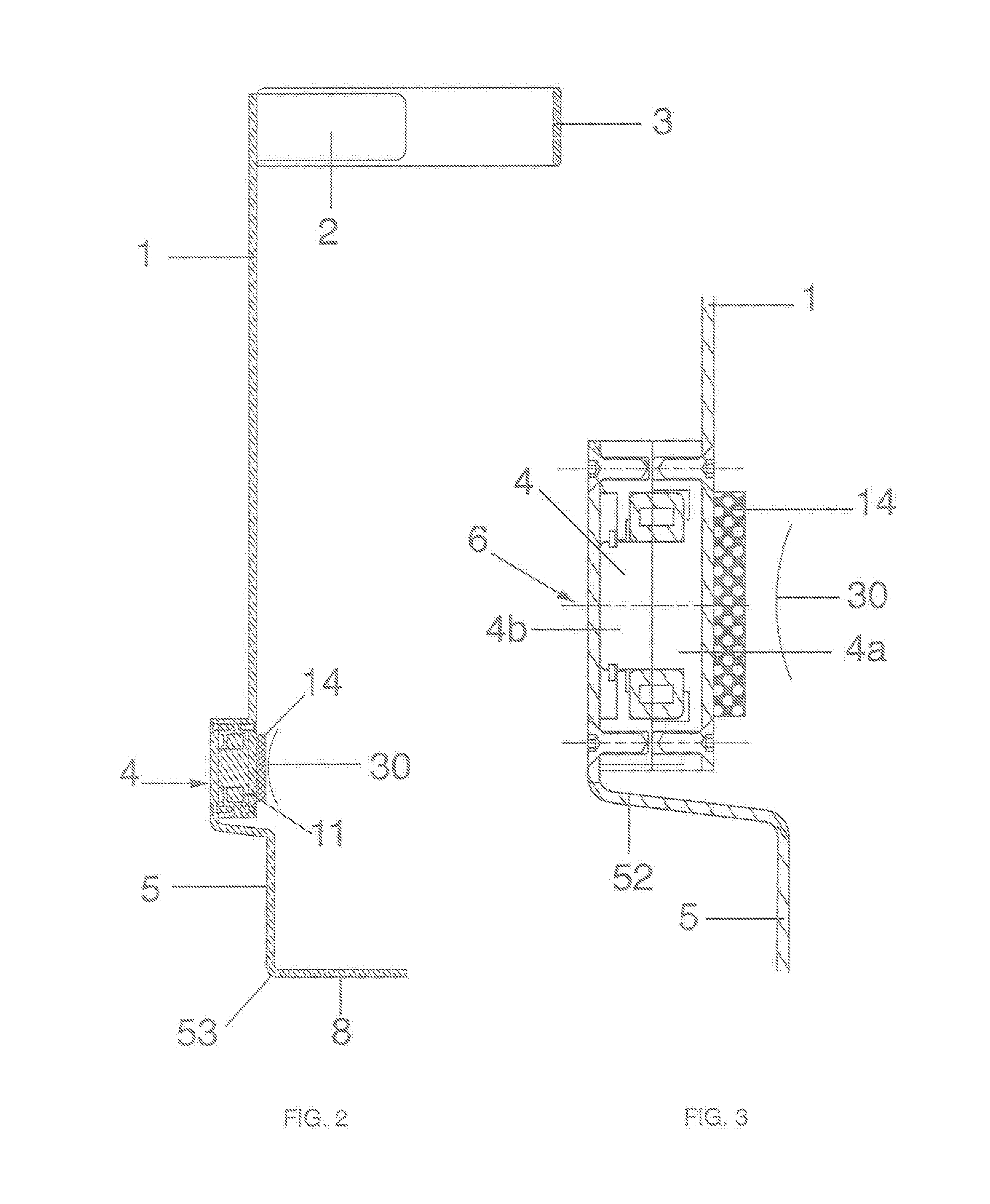
[0013]FIG. 2 is a vertical section taken on line A-A of FIG. 1;

[0014]FIG. 3 shows the primary joint for moving the foot;

[0015]FIG. 4 shows the orthosis with the bracket in a state of maximum lifting;

[0016]FIG. 5 shows the elastic device;

[0017]FIG. 6 shows a diagram of the elongation curve of a magnetic spring comprised in the device of the invention;

[0018]FIG. 7 shows a diagram of a elongation curve of a standard steel spring.

[0019]Reduced to its essential construction, the orthosis comprises: a vertical, substantially flat bar (1), whose upper end (10) is anchored to a collar (2) to be fastened by common automatic means to the leg (3) above the user's calf, and fixed to the lower end of said bar is a rolling bearing (4) to which a flat cantilevered arm with curvilinear profiled arm (5) is hinged to be osc...


PUM


Abstract

Dynamic orthosis for drop foot, with a vertical flat, rigid bar (1) solid to a collar (2) of a patient's leg (3), and whose lower free end is solid do a bearing (4) which is to take position in front of the internal malleoulus (30) of the user and to constitute the joint of a cantilevered arm (5) whose free end is solid to a bracket (8) for the foot, and whose motion required for lifting the foot during the deambulation is obtained by the force Fs generated by a magnetic spring (9) with the interposition of a rod (94); the required lifting force Fs being produced by more pairs of magnets (92) vertically lined up and with the same polarity being juxtaposed to allow using their mutual repulsive force.The loading phase of the spring (9) corresponds to the pressure of the foot onto the ground and, therefore, to the maximum moment onto the malleoulus exerted by the compression of the magnets upon the movement thereof close to each other.On the other hand, the next release phase of the spring, that is, the spontaneous movement of the magnets away from each other—which takes place upon the detachment of the foot from the ground—that is, when the moment onto the malleoulus is minimum, is cause for a clockwise rotation of the arm (5) and, consequently, the lifting of the bracket (8) along with the foot.

Description

TECHNICAL FIELD[0001]The invention refers to those orthosis intended to make up for the loss of functionality of the paralyzed muscles in drop foot and to allow a correct walking thereof.STATE OF THE ART[0002]It is known that the paralysis is the loss of the capacity of movement of a body segment. The paralyses can be divided into central and peripheral according to whether the first or second neuron of motion is affected.[0003]Central paralyses caused by ictus, tumors, infectious neurologic, systemic diseases and others, after a first stage of muscle hypotonia, evolve in the majority of the cases to an increase of the muscle tone (hypertonia), so that they are called spastic paralyses. One characteristic thereof is the presence of clones, that is, global involuntary and non-oriented movements of a limb as a consequence of an alteration of the motion schemes.[0004]Peripheral paralyses caused by herniated vertebral discs, tumors, degenerative disease of the second neuron and others, ...

Claims


Application Information

Patent Timeline
IPC IPC(8): A61F5/01
CPCA61F5/0127A61F2005/0169A61F2005/0179A61F5/0113A61F2002/6863
Inventor GIONTELLA, MASSIMO
Owner MP S R L IN CONCORDATO PREVENTIVO
Learn More